7
Factory Default Settings
80/108 CLS Pro 600 – Line and Contrast Sensor
NOTICE
Caution!
You are only allowed to modify the device address if authorized to
do so by the manufacturer!
DANGER
Danger from the power supplies!
The control panel’s connecting cable plug must be disconnected
from the controller before you open the control panel!
Setting the Device Address:
1. Unplug the control panel connecting cable from the sensor.
2. Carefully remove stopper B from the rear of the control panel.
3. Check the S1 rotary switch setting The S1 rotary switch must be
set to position 1.
4. Switch the S1 rotary switch to position 1 if necessary.
5. Replace the stopper.
6. Reconnect the control panel connecting cable to the sensor.
7.2 Terminator Resistors
The internal terminator resistors for the sensor and the control
panel were switched on in the factory. The settings usually do not
have to be modified. Check the terminator resistor settings if mal-
functions or non-defined sensor or operator panel processes oc-
cur or re-occur after the devices have been changed.
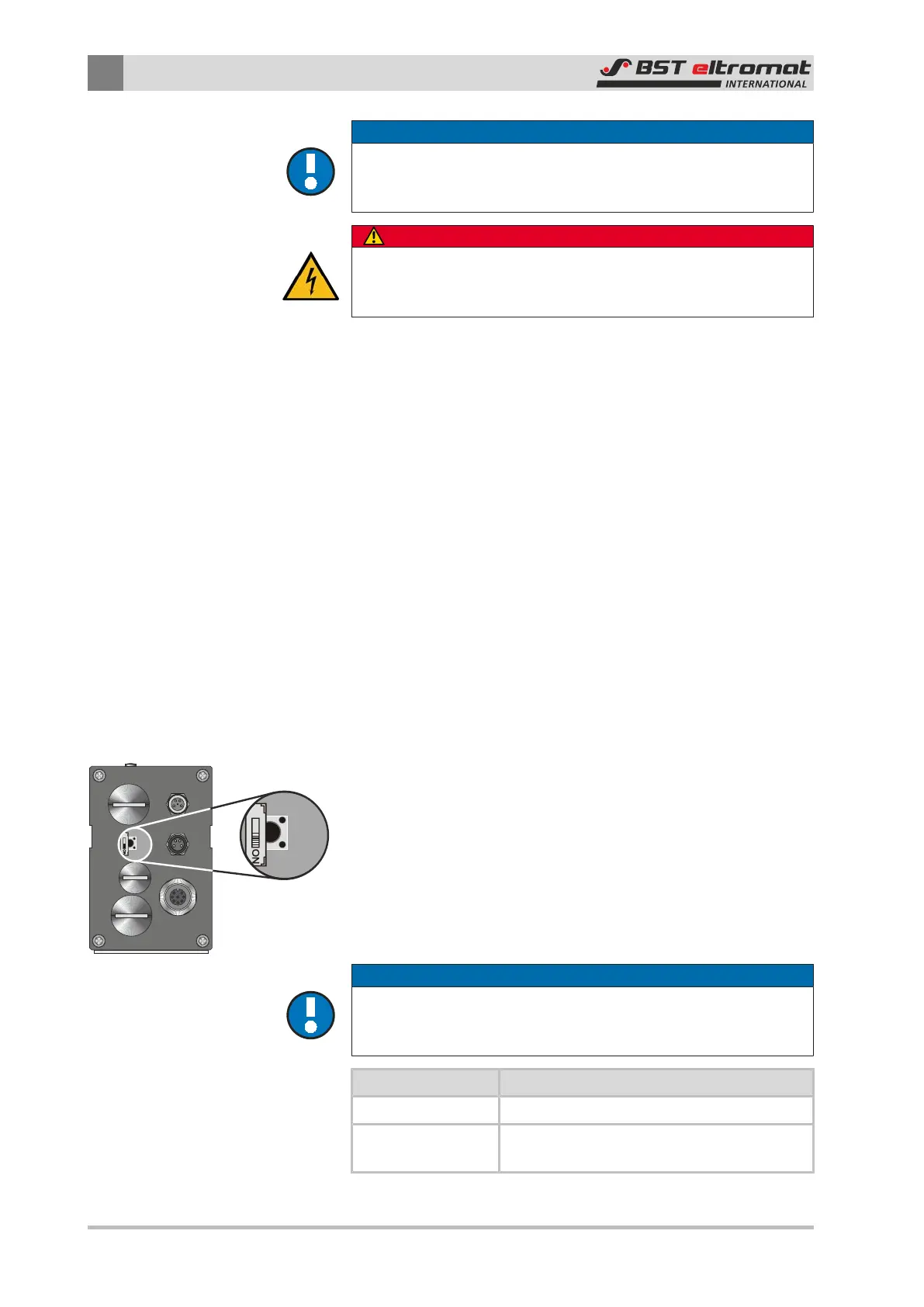
7.2.1 Sensor Terminator Resistors
The sensor’s internal terminator resistor is switched on or off us-
ing switch S3. The current setting is displayed in the System info
sub-menu as Can Resistor Sensor (see Section 6.7.5).
NOTICE
Caution
The terminating resistor should only be switched off after first ob-
taining agreement from the manufacturer!
Switch S3 Function
OFF Internal terminating resistor switched off
ON
Internal terminating resistor switched on
(default factory setting)