3
Assembly
22/108 CLS Pro 600 – Line and Contrast Sensor
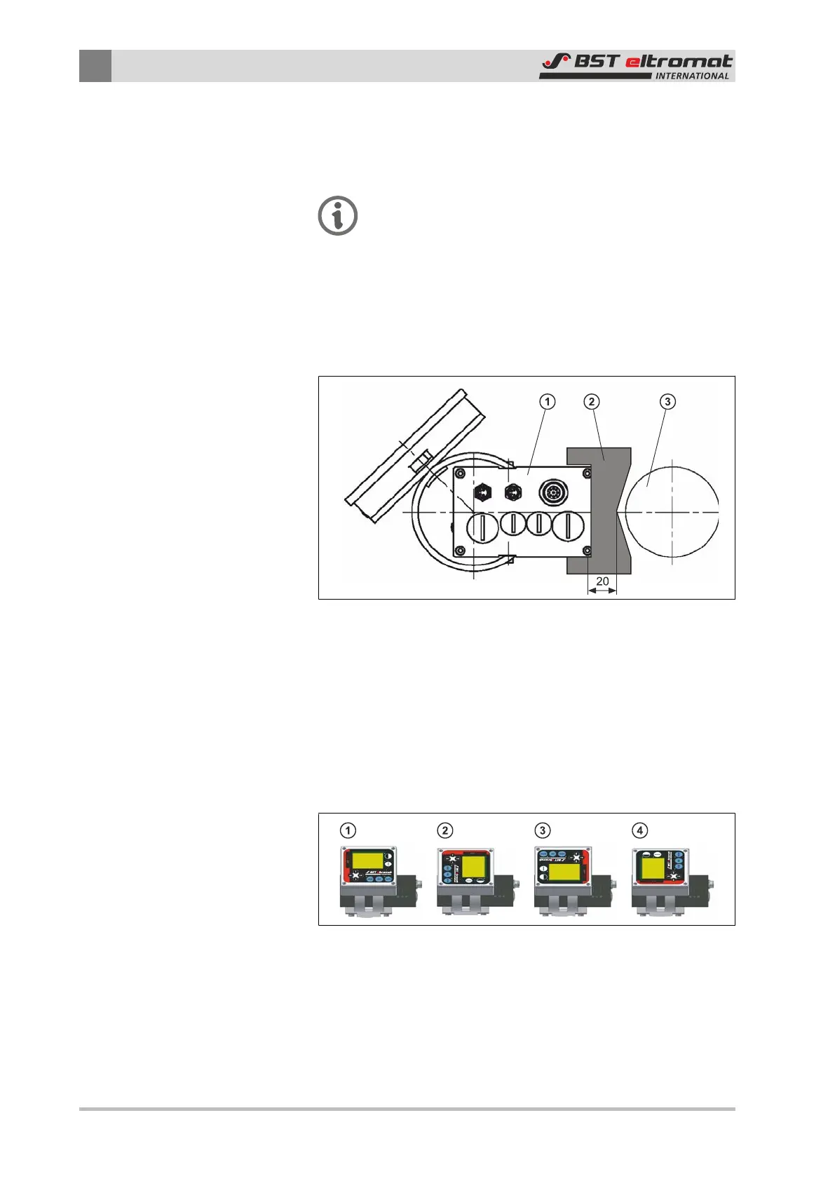
3.2.4 Setting the Gap Between the Sensor and the Sensing Roller
The optimum gap between the sensor and the sensing roller can
be set up using the measuring window protective packaging.
Please note:
The measuring window protective packaging is an integ-
ral part of the overall packaging!
In this case you must attach the protective packaging to area
around the sensor enclosure’s measuring window.
Slide the sensor along in the sensing roller direction until the pro-
tective packaging lies up against the sensing roller (see drawing).
Pull the protective packaging out to one side afterwards.
Fig.15: Setting the Gap Between the Sensor and the Sensing Roller
①
Sensor Enclosure
②
Protective Packaging
③
Scanning Roller
3.2.5 Turning the Control Panel
The control panel can be mounted on the sensor in four different
positions (each one offset by 90° from the other) (see diagram).
Fig.16: Turning the Control Panel
The sensor is prepared for installation in position ① when de-
livered from the factory.