Assembly
3
CLS Pro 600 – Line and Contrast Sensor 23/108
The control panel mounting position must be altered accordingly
if the sensor’s control panel cannot be operated correctly due to
the existing installation situation. The relevant procedure is de-
scribed in the following.
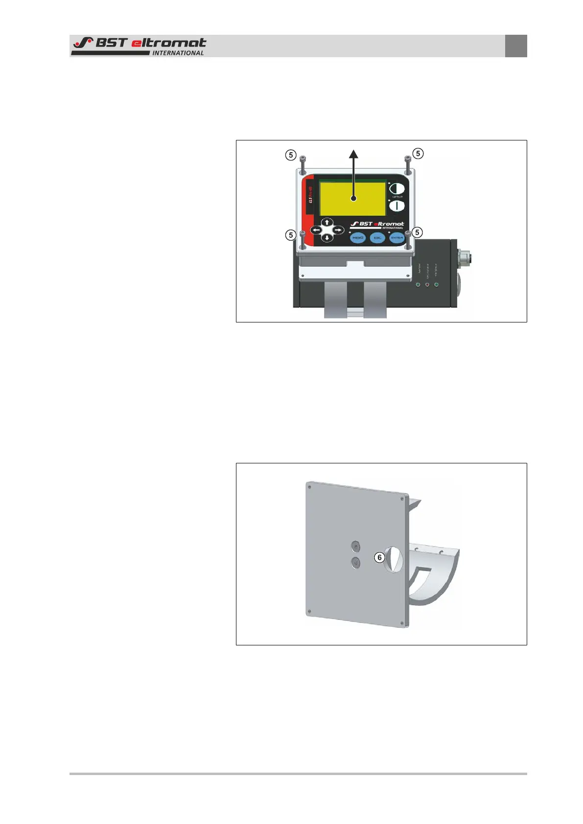
Fig.17: Fastening Screws
⑤
Fastening Screws
1. Unscrew the four control panel fastening screws.
2. Carefully pull the control panel upwards and away from the
sensor.
3. Turn the control panel into the required position (see illustra-
tion above).
Fig.18: Cut-out
⑥
Cut-out