2-34
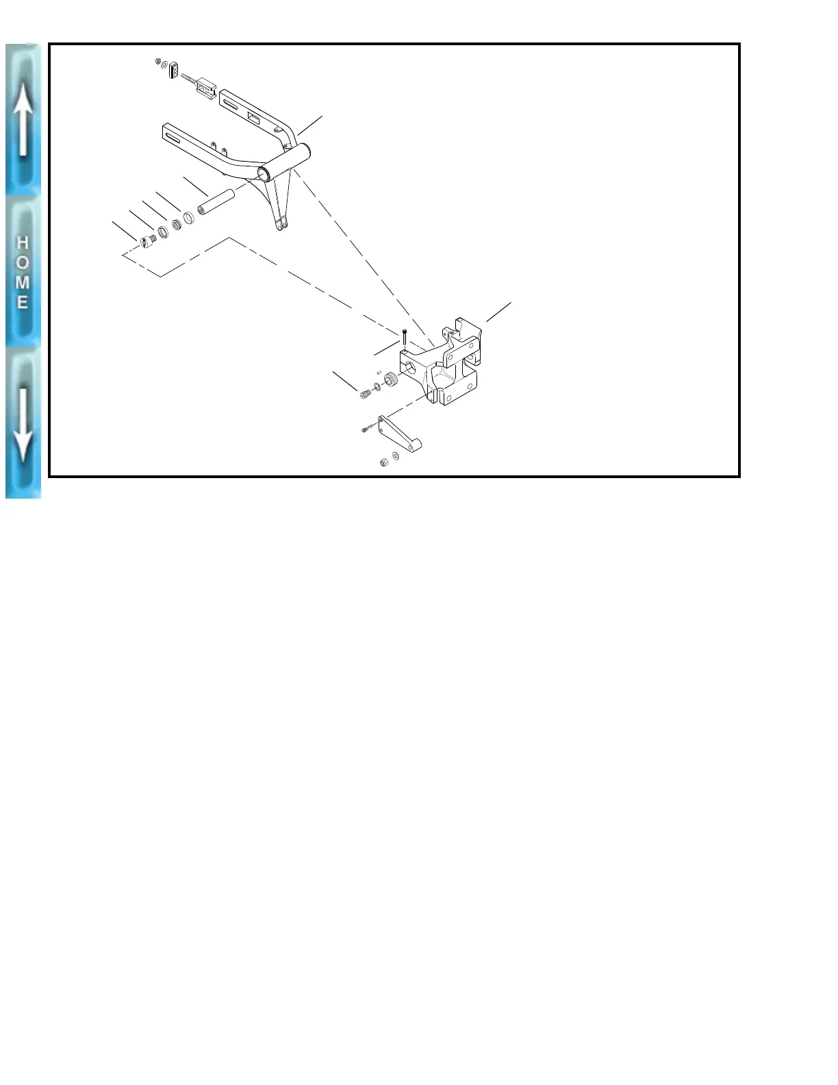
Figure 2-37. Swingarm Assembly and Swingarm Mount Block
2
1
3
4
6
7
8
5
1. Bearing adjusting bolt (2)
2. Swingarm seal (2)
3. Roller bearing (2)
4. Roller bearing cup (2)
5. Pivot shaft
6. Swingarm
7. Swingarm mount block
8. Pinch screw (2)
9. Isolator screw (2)
10. Rubber isolator (2)
b0210x2x
9
NOTE
Timkin roller bearing assemblies should be replaced as a
unit. Do not intermix components. Mark all components so
they may be correctly installed.
2. Coat bearing components with WHEEL BEARING
GREASE (Part No. HD-99855-89) and assemble.
1
CAUTION
Pivot shaft (5) must be installed between inner races (3)
or bearing failure can result.
3. Install a
new
swingarm seal (2) flush to the swingarm.
4. Apply LOCTITE ANTI-SEIZE LUBRICANT to pivot shaft
threads.
5. Install one bearing adjustment bolt (1) into pivot shaft (5).
Bottom out the adjustment bolt.
6. Slide swingarm assembly into position.
7. Slide pivot shaft assembly through mount block and
swingarm. Install the opposing bearing adjustment bolt
(1) using PIVOT SHAFT BEARING ADJUSTER (Part No.
B-41175).
8. Tighten one pinch screw (8) into swingarm mount block.
Do not tighten the other pinch screw (8) at this time.
INSTALLATION
1. Adjust swingarm preload. Using a scale as shown in Fig-
ure 2-40. Preload should measure 3.5-5.5 lbs (1.6-
2.5 kg).
2. Remove both pinch screws (8). Apply LOCTITE
THREADLOCKER 242 (blue) to pinch screw threads.
3. Check that swingarm is centered between mounts.
Torque pinch screws (8) to 27-30 ft-lbs (36.6-40.7 Nm).
4. Install rubber isolators and bolts. See SECONDARY
DRIVE BELT in Section 6.
5. Attach tie bars to the frame in the following order. Torque
to 30-33 ft-lbs (40.7-44.7 Nm)
a. Front tie bar. Clutch cable clamp holds cable on air
cleaner side of motor.
b. Top tie bar.
c. Rear tie bar. Tie bar must be horizontal and below
frame tab.
6. Install carburetor. See CARBURETOR, INSTALLATION
in Section 4.
7. Install muffler and exhaust header. See EXHAUST SYS-
TEM, ASSEMBLY/INSTALLATION on page 2-50.
8. Install air cleaner. See AIR CLEANER, INSTALLATION in
Section 4.