4-21
DISASSEMBLY/ASSEMBLY
1
WARNING
Even with the fuel tank completely drained, a small
amount of gasoline may leak from the bore when the fuel
supply valve is loosened or removed. Thoroughly wipe
up any spilt fuel immediately and dispose of rags in a
suitable manner. Gasoline can be extremely flammable
and highly explosive. Inadequate safety precautions may
result in personal injury.
1. If the fuel supply valve requires cleaning or repair, see
FUEL SUPPLY VALVE, REMOVAL on page 4-22.
2. See Figure 4-21. Remove fuel filler cap (3) and O-ring (4).
3. Remove vent valve fitting (10) and vent valve (8).
4. Remove self-tapping screws (5) from fuel cap flange (9).
5. Remove fuel cap flange and fuel cap boot (6).
6. Assemble in reverse order.
a. Apply HYLOMAR to fuel cap boot, fuel cap flange
and top of fuel tank.
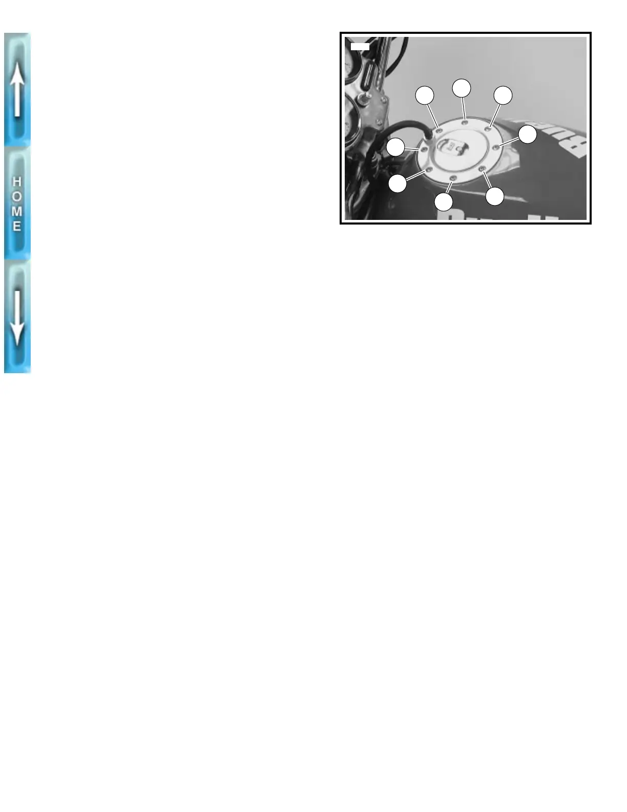
b. See Figure 4-22. Tighten screws to 22-25
in-lbs
(2.5-2.8 Nm) in the order shown.
CLEANING, INSPECTION
AND REPAIR
1
WARNING
An open flame or spark may cause a fuel tank explosion
if all traces of fuel are not purged from the tank. Use
extreme caution when servicing fuel tanks. Inadequate
safety precautions may result in personal injury.
Clean tank interior with commercial cleaning solvent or a soap
and water solution. Plug fuel tank openings. Shake tank to agi-
tate the cleaning agent. Thoroughly flush fuel tank after clean-
ing. Allow tank to air dry. Carefully inspect fuel hose for
damage, wear or general deterioration. Replace as necessary.
INSTALLATION
1. See Figure 4-21. Place fuel tank on frame. Install fuel
tank screw (1) and washer (2). Tighten to 9-11 ft-lbs
(12.2-14.9 Nm).
1
CAUTION
Avoid pinching wiring harness and vent hose between
fuel tank and frame during tank installation. Pinched
hoses will negatively affect vehicle operation.
2. Connect vent hose (11) to vent valve fitting (10). Clamp
hose to fitting with a
new
cable strap (12).
3. Connect fuel hose to fuel supply valve with a
new
clamp
and HOSE CLAMP PLIERS (Part No. HD-41137)
1
WARNING
After installing seat, pull upward on front of seat to be
sure it is locked in position. If seat is loose, it could shift
during vehicle operation and startle the rider, causing
loss of control and personal injury.
4. Install seat. See SEAT, INSTALLATION in Section 2.
5. Fill fuel tank with fuel supply valve turned OFF.
6. Open fuel supply valve and carefully inspect for leaks.
Turn valve OFF after the inspection is performed.
Figure 4-22. Tightening Flange
6
3
7
5
2
4
8
1
5742