2-46
SPEEDOMETER AND TACHOMETER
GENERAL
Replace the speedometer or tachometer if the unit is not
working properly. These instruments are not repairable. How-
ever, before replacing the instrument check that the problem
is not caused by a faulty cable or loose wire connection.
REMOVAL
Speedometer
1. Detach windscreen from mounts. See WINDSCREEN,
REMOVAL on page 2-56.
2. See Figure 2-54. Loosen and remove the speedometer
cable (5) from the speedometer.
3. Remove nuts and lockwashers (4) from speedometer
cover (1).
4. Straighten reset cable cotter pin and remove. Discard
pin. Detach reset cable assembly from speedometer.
5. Remove cover. Remove wires from clamp inside cover.
6. Detach ground wire.
7. See Figure 2-55. Disconnect wire terminals from back of
speedometer. Pull bulbs (3) from bores.
8. Remove speedometer (1) through front of instrument
support (8).
Tachometer
1. Detach windscreen from mounts. See WINDSCREEN,
REMOVAL on page 2-56.
2. See Figure 2-54. Remove nut and lockwasher (4) from
tachometer cover (2).
3. Remove nut on windscreen mount (3). Remove wind-
screen mount from tachometer cover.
4. Remove tachometer cover.
5. Remove ground wires from bottom stud.
6. See Figure 2-55. Disconnect wire terminals from back of
tachometer. Pull bulbs (3) from bores.
7. Remove tachometer (2) through front of instrument sup-
port (8).
Instrument Support
1. Remove speedometer and tachometer.
2. See Figure 2-55. Remove knurled nut (5), washer (6) and
odometer reset cable.
3. Pull indicator lights assembly (4) out towards the head-
lamp. Pull bezel (19) out towards the tail lamp.
4. Remove two screws (7).
5. Remove instrument support.
INSTALLATION
Speedometer
1. See Figure 2-55. If removed, install instrument support
(8). Slide speedometer into instrument support.
2. Attach ground wire with screw and lockwasher.
3. Connect wire terminals on back of speedometer. Insert
bulbs into bores at back of speedometer.
4. See Figure 2-54. Using a new cotter pin, connect reset
cable assembly (6) to speedometer.
5. Place speedometer cover over speedometer. Tighten
nuts and lockwashers (4).
6. Connect speedometer cable (5) to speedometer.
7. Attach windscreen. See WINDSCREEN, INSTALLATION
on page 2-56.
Tachometer
1. See Figure 2-55. If removed, install instrument support
(8). Slide tachometer into instrument support (8).
2. Connect wire terminals on back of tachometer. Insert
bulbs into bores.
3. Attach ground wire.
4. See Figure 2-54. Slide tachometer cover (2) over
tachometer. Install nut and lockwasher (4).
5. Install windscreen mount (3) with nut.
6. Attach windscreen. See WINDSCREEN, INSTALLATION
on page 2-56.
Instrument Support
1. See Figure 2-55. Attach instrument support to mounts
using two screws (7). Tighten screws to 7-9 ft-lbs (9.5-
12.2 Nm).
2. Install odometer reset cable using washer (6) and
knurled nut (5).
3. Insert bezel (19) through instrument support. Attach indi-
cator lights assembly (4) to bezel.
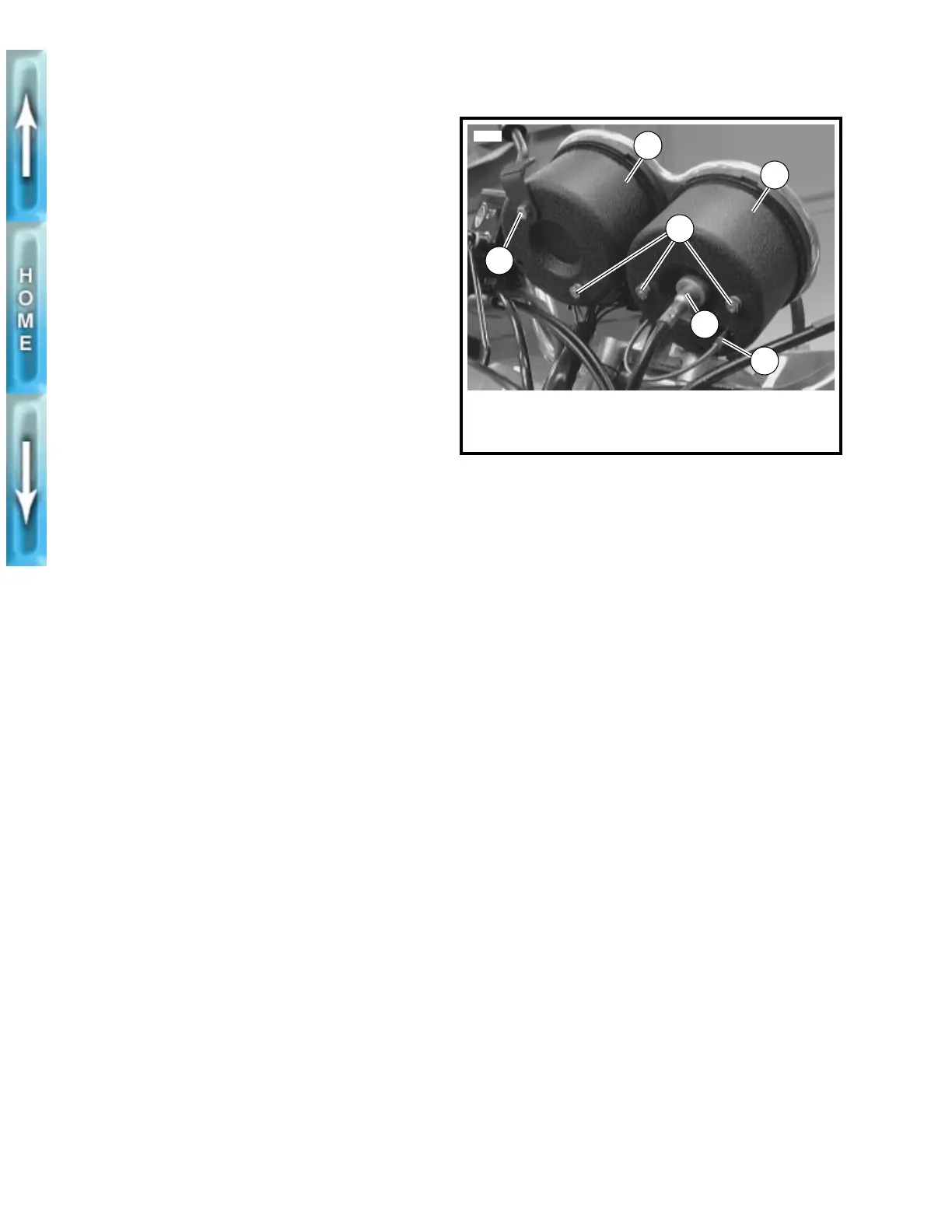
Figure 2-54. Instruments
5716
2
3
6
1. Speedometer cover
2. Tachometer cover
3. Windscreen mount
4. Nut and lockwasher (3)
5. Speedometer cable
6. Odometer reset cable
1
4
5