4-12
ADJUSTMENT
Idle
See IGNITION TIMING in Section 1.
Enrichener Control
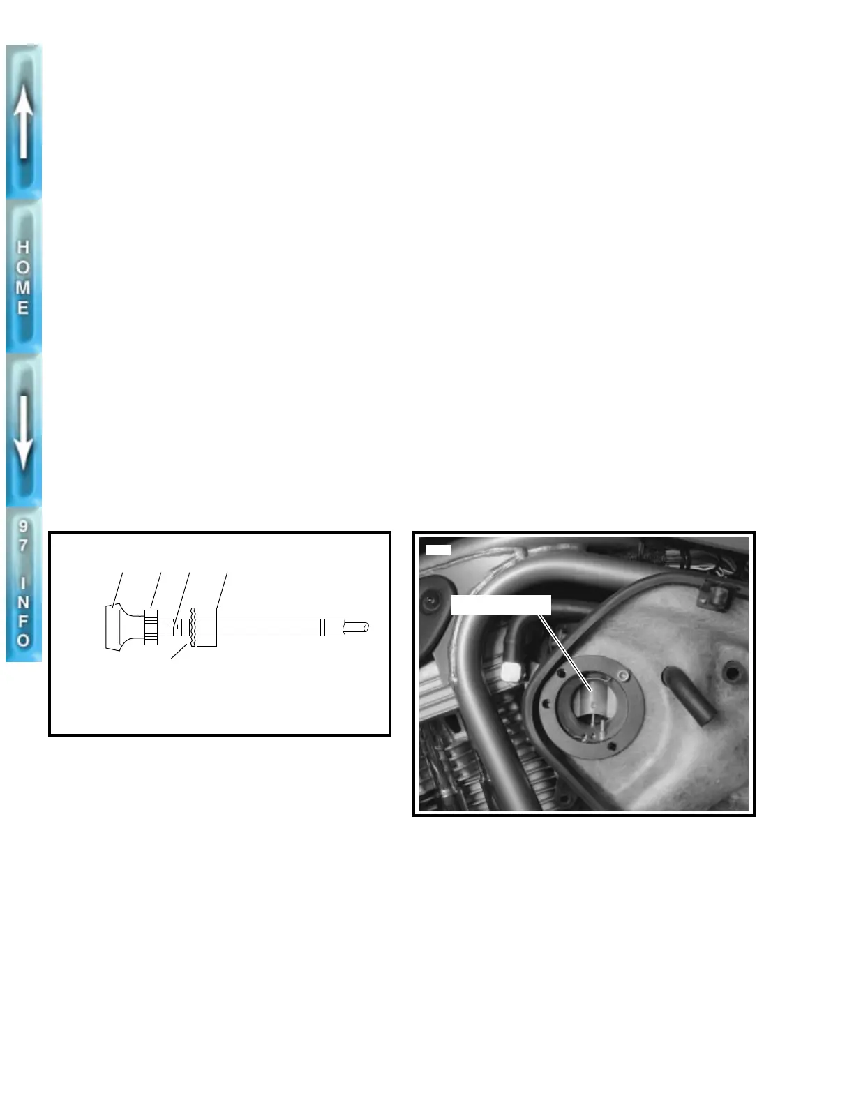
See Figure 4-9. Check enrichener operation. Enrichener knob
(1) should open (and remain open) and close without binding.
Plastic nut (2), next to the enrichener knob, controls the sliding
resistance of the enrichener control cable within the cable con-
duit. If adjustment is needed, perform the following:
1. Loosen hex nut (5) at backside of mounting bracket.
2. Move cable assembly free of slot in mounting bracket.
3. Hold cable assembly at flats (4) with a wrench. Adjust
resistance until knob slides outward and remains fully
open without assistance. Knob must also slide inward
unaided.
a. Turn plastic nut (2) by hand counterclockwise
(reducing sliding resistance).
b. Turn plastic nut clockwise (increasing sliding resis-
tance).
4. Position cable assembly into slot in mounting bracket.
Tighten hex nut at backside of bracket.
NOTE
Do not lubricate the cable or inside of conduit. The cable must
have friction to work properly.
Float Level
1. Remove carburetor and place on a flat, clean surface on
engine manifold side. This is the “base.” Tilt carburetor
counterclockwise 15˚ to 20˚ from base until float comes
to rest. See Figure 4-11.
NOTE
If carburetor is tilted less than 15˚ or more than 20˚, your
measurements will be inaccurate.
2. Use a vernier or dial caliper depth gauge to measure
from the carburetor flange face to the perimeter of the
float. Be careful not to push on float while measuring.
The measurement must be 0.413-0.453 in.
(10.49-11.51 mm). If measurement is not within given
dimension, remove float and carefully bend tab in order
to reposition float at proper level.
3. Install float and recheck setting.
4. Install float bowl. Install carburetor as described in CAR-
BURETOR, INSTALLATION on page 4-17.
OPERATION CHECK –
VACUUM PISTON
Opening Malfunction
1
WARNING
While observing piston slide movement, be sure to main-
tain a safe distance from the carburetor and to wear suit-
able eye protection. An unexpected engine backfire could
cause personal injury.
1. See Figure 4-10. Test vacuum piston as follows.
a. Remove air cleaner cover and snorkel.
b. Start engine running.
c. Twist throttle control partially open and closed sev-
eral times.
Observe whether or not vacuum piston has upward
movement. If piston does not rise, see VACUUM PIS-
TON ASSEMBLY TROUBLESHOOTING on page 4-4.
2. With engine not running, lift vacuum piston with finger.
Feel whether piston lifts fully and smoothly or whether
there is a binding condition.
Closing Malfunction
1. See Figure 4-10. With engine not running, lift vacuum
piston to full open position, then release. Observe
whether piston slides downward smoothly and fully to
stop.
2. Observe position of piston slide at its lowest downward
point. Lower edge of slide should rest at horizontal
groove at lower end of slide track. See VACUUM PIS-
TON ASSEMBLY TROUBLESHOOTING on page 4-4 if
problems are noted.
Figure 4-9. Fuel Enrichener Control
1. Enrichener knob
2. Plastic nut
3. Lockwasher
4. Flat
5. Hex nut
b0090c4x
21
3
4 5
Figure 4-10. Vacuum Piston
Vacuum piston
5679