2-53
SPROCKET COVER
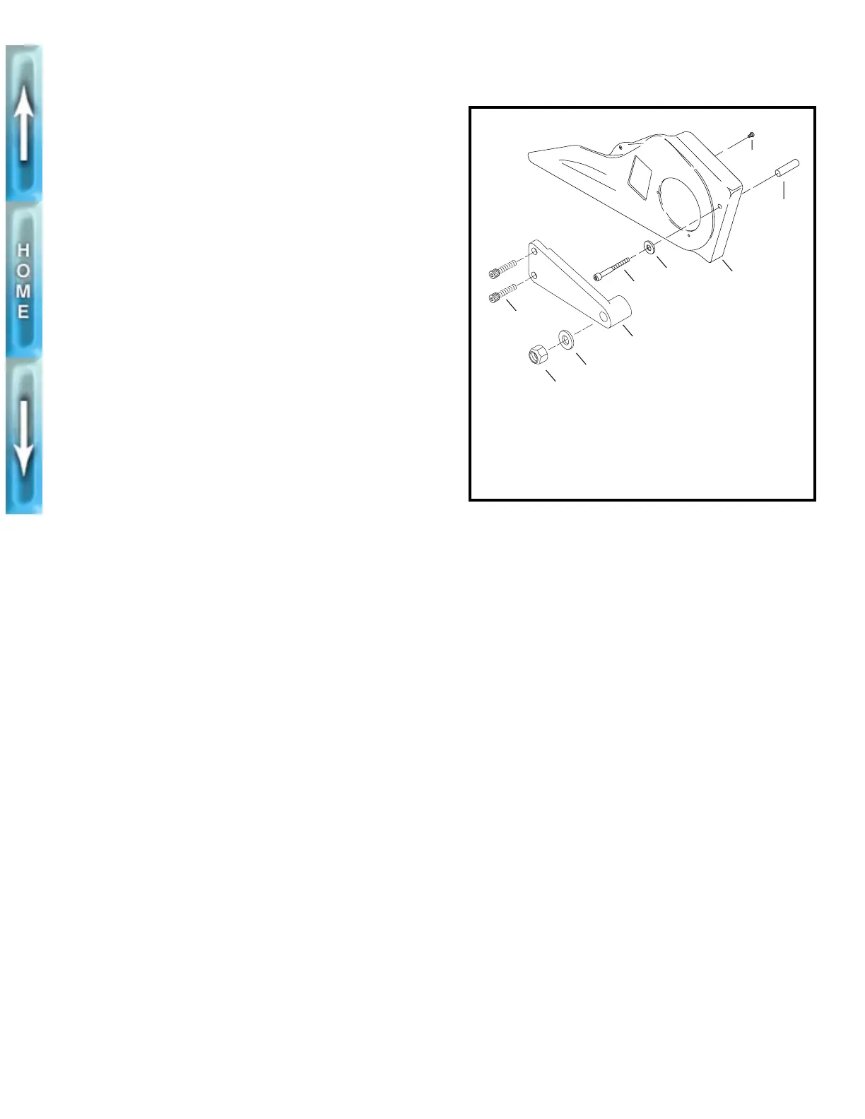
REMOVAL/DISASSEMBLY
1. See Figure 2-60. Remove nut (1) and washer (2).
2. Remove two screws (3).
3. Remove sprocket cover screw (5), washer (6) and
spacer (8).
4. Remove swingarm drive/support (4) and sprocket cover
(7) as an assembly.
5. Remove two screws (9) to separate sprocket cover from
swingarm/drive support.
ASSEMBLY/INSTALLATION
1. See Figure 2-60. If removed, attach sprocket cover to
swingarm/drive support with two screws (9). Tighten
screws to 12-17 in-lbs (1.4-1.9 Nm).
2. Install sprocket cover assembly with screw (5), washer (6)
and spacer (8). Tighten screw to 4-6 ft-lbs (5.4-8.6 Nm).
3. Install screws (3). Tighten to 20-25 ft-lbs (27.1-33.9 Nm).
4. Install nut (1) and washer (2). Tighten nut to 30-35 ft-lbs
(40.7-47.4 Nm).
Figure 2-60. Sprocket Cover
1. Nut
2. Washer
3. Screw (2)
4. Swingarm/drive
support
5. Sprocket cover crew
6. Washer
7. Sprocket cover
8. Spacer
9. Screw (2)
1
2
3
4
5
6
7
8
9
b0204x2x