3-12
3. Rotate crankshaft until both valves are closed on head
being repaired.
4. Remove two 5/16 in. rocker arm retaining bolts (12) at
push rod end.
5. Remove remaining fasteners and washers (13, 14 and
15) holding lower rocker arm cover to cylinder head.
6. Remove lower rocker cover (18).
NOTE
Remove lower rocker boxes as an assembly; then disassem-
ble as required.
1
CAUTION
Mark rocker arm shafts for reassembly in their original
positions. Valve train components must be reinstalled in
their original positions to prevent accelerated wear and
increased valve train noise.
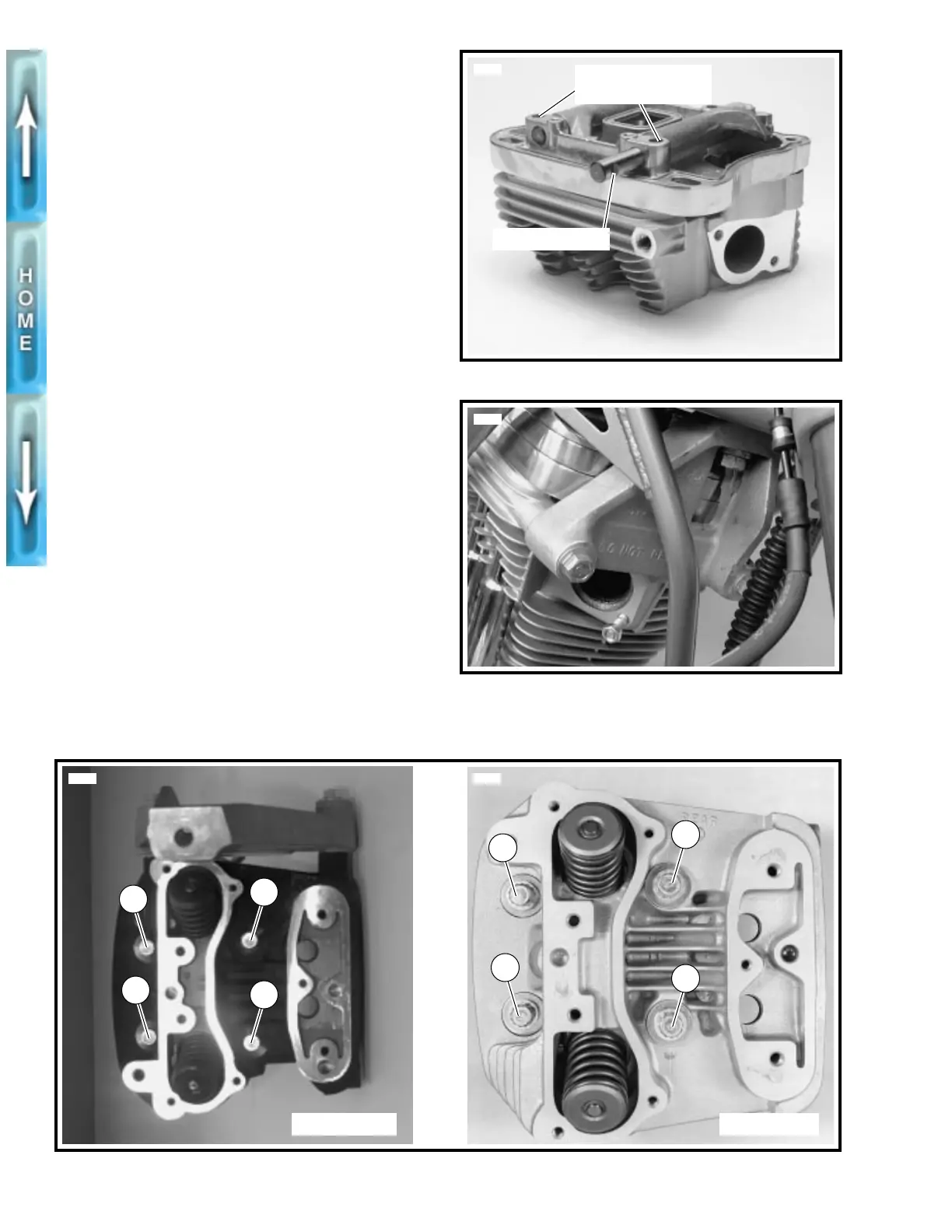
7. See Figure 3-6. Remove rocker arm shafts by tapping
them out using a hammer and a soft metal punch.
8. See Figure 3-5. Remove rocker arms (10, 11); mark
them for reassembly in their original locations.
1
CAUTION
Distortion to the head, cylinder and crankcase studs may
result if head screws are not loosened (or tightened)
gradually in the sequence shown in Figure 3-8.
9. See Figure 3-8. Loosen each head screw 1/8-turn follow-
ing the sequence shown.
1
CAUTION
See Figure 3-7. Do not attempt to remove the front isola-
tor mount from front cylinder head. Isolator mount is an
integral component and is not meant to be removed
unless absolutely necessary. Repeated removals and
installations will damage cylinder head threads.
Figure 3-6. Removing Rocker Arm Shafts
Figure 3-7. Front Isolator Mount Warning
5698
Retaining notch
Position of rocker
arm retaining bolts
5740
Figure 3-8. Head Screw Loosening/Tightening Sequence
1
5112 2857a
3
4
2
1
3
4
2
Front cylinder Rear cylinder