37
WIRING HARNESS
MODEL YEAR CHANGE
The following changes were made to the wiring harness for
1997 model year motorcycles.
●
New connectors and a different pin numbering sequence
for the right handlebar switch [P1] and the left handlebar
switch [P6]. See HANDLEBAR SWITCHES on page 33.
●
Longer wires leading to the horn to accommodate the
new mounting position.
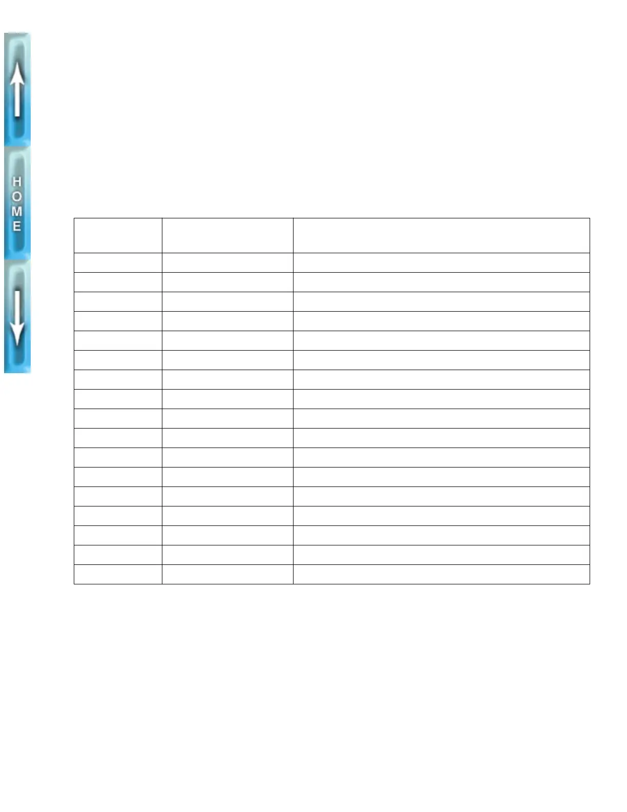
Table 3. Electrical Connectors
CONNECTOR
NUMBER
DESCRIPTION COMPONENT(S)
[P1] 4-place connector right handlebar switch housing-ignition power, module and starter
[P2] 2-place Amp Multilock front brake switch
[P3] 12-place Amp Multilock instruments and indicator lamps
[P4] 4-place Amp Multilock headlamp
[P5] 2-place Amp Multilock clutch switch
[P6] 8-place connector left handlebar switch housing-horn, turn signals, lights
[P7] 2-place Deutsch vacuum-operated electric switch
[P8] 4-place PED ignition/headlamp switch
[P9] 4-slot fuse block four 15 amp fuses-ignition, instruments, lights and accessories
[P10] 8-place Deutsch ignition module
[P11] 8-place Amp Multilock tail lamp and rear turn signals
[P12] 4-place relay ignition relay
[P13] 4-place relay starter relay
[P14] 2-place Amp Multilock side stand switch
[P15] 2-place Amp Multilock license plate light
[P16] 3-place Deutsch timer and pickup
[P17] 2-place plug voltage regulator