7-42
NEUTRAL INDICATOR SWITCH
GENERAL
See Figure 7-43. The neutral indicator switch (1) is threaded
into the transmission portion of the right crankcase half (2); it
is immediately forward of the main drive gear shaft (3). The
sprocket cover must be removed to test the switch. If switch
requires replacement, secondary drive belt and transmission
sprocket must also be removed; there is not enough clear-
ance to allow the removal of the switch without first removing
the transmission sprocket.
A pin on the shifter drum contacts the neutral indicator switch
plunger, completing the neutral indicator circuit. The switch is
not repairable. Replace the switch if it malfunctions.
TESTING
1. Remove sprocket cover. See SPROCKET COVER in
Section 2.
2. See Figure 7-43. Disconnect wire lead from neutral indi-
cator switch (1).
3. With ignition switch ON, touch the neutral indicator wire
lead to a suitable ground.
a. If indicator lamp lights, then problem is at indicator
switch. Replace switch.
b. If indicator lamp does not light, then problem is else-
where in circuit (i.e. indicator lamp burned out, loose
connection, or faulty wiring).
c. After testing, connect wire lead to indicator switch.
4. Install sprocket cover. See SPROCKET COVER in Sec-
tion 2.
REMOVAL/INSTALLATION
1. Verify that the ignition/headlamp switch is turned to
LOCK.
2. Remove sprocket cover. See SPROCKET COVER in
Section 2.
3. See Figure 7-43. Place transmission in first gear.
Remove two socket head screws (7) and lockplate (6).
1CAUTION
Transmission sprocket nut has left-hand threads. Turn
nut clockwise to loosen and remove from main drive gear
shaft. Transmission sprocket nut will be damaged if
turned counterclockwise to remove.
4. Remove transmission sprocket nut (5) from main drive
gear shaft (3).
5. Decrease secondary drive belt tension by loosening axle
adjusting nuts. See REAR BELT DEFLECTION in Sec-
tion 1. Remove transmission sprocket (4) (with second-
ary drive belt) from main drive gear shaft (3).
6. Remove wire lead from neutral indicator switch (1).
Remove switch from right crankcase half (2).
7. Apply a light coating of LOCTITE THREADLOCKER 242
(blue) to new neutral indicator switch (1) threads. Install
switch in crankcase, and tighten switch to 3-5 ft-lbs (4.0-
6.8 Nm). Connect wire lead to switch.
8. Install transmission sprocket (4) (with secondary drive
belt) onto main drive gear shaft (3). See TRANSMIS-
SION INSTALLATION AND SHIFTER PAWL ADJUST-
MENT in Section 6.
9. Install sprocket cover. See SPROCKET COVER in Sec-
tion 2.
10. Adjust secondary drive belt tension. See REAR BELT
DEFLECTION in Section 1.
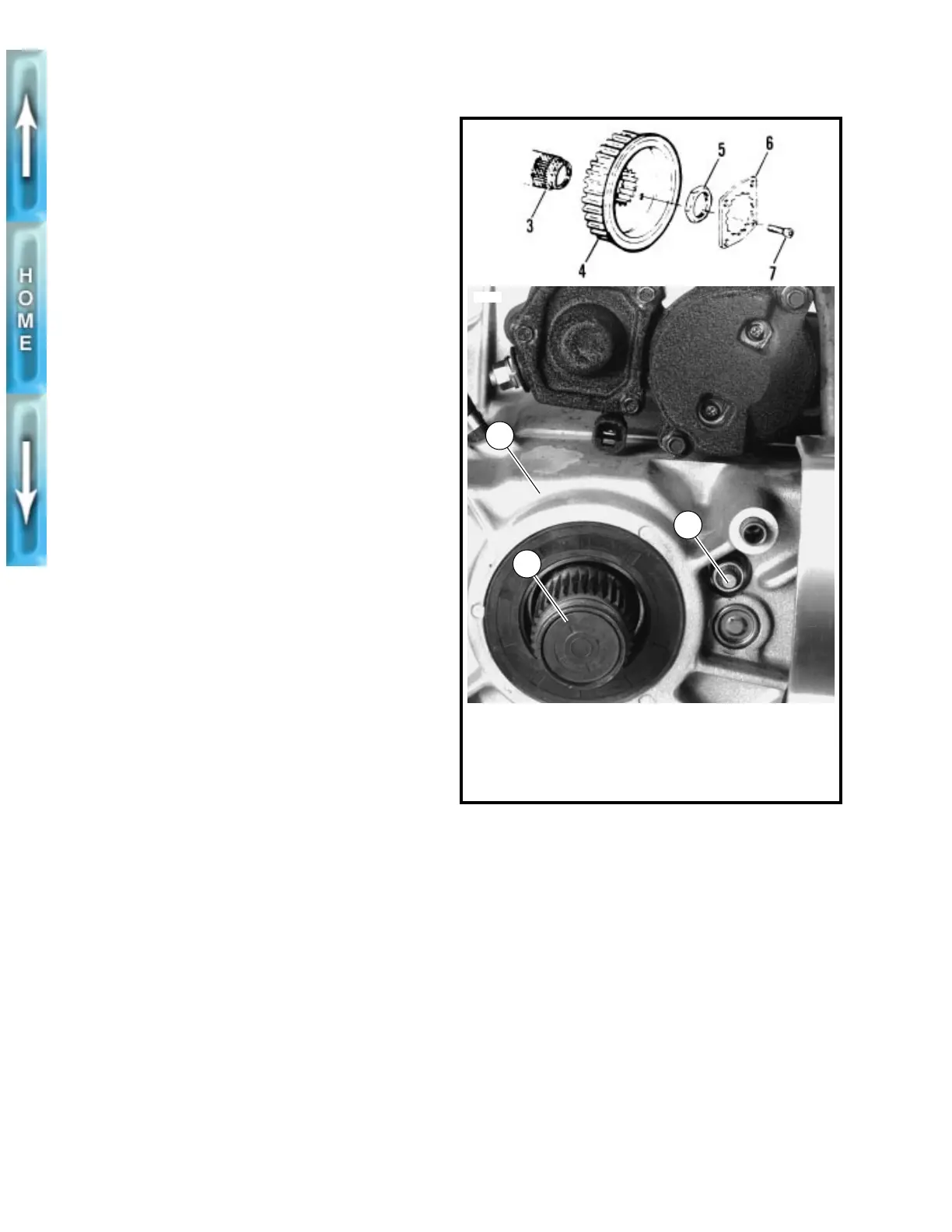
Figure 7-43. Neutral Indicator Switch
1. Neutral indicator
switch
2. Right crankcase half
3. Main drive gear
shaft
xlh0733
3
3553
1
2
4. Transmission sprocket
5. Transmission sprocket
nut (LH threads)
6. Lockplate
7. Socket head screw (2)