6-16
TRANSMISSION CASE
GENERAL
The rear compartment of the left and right crankcase halves
form the transmission case. An access cover (door) allows
removal of transmission components without removing the
engine or disassembling (splitting) the crankcase.
REMOVAL
1. Raise rear wheel off floor using REAR WHEEL SUP-
PORT STAND (Part No. B-41174).
2. Remove rear fender. See FENDERS in Section 2.
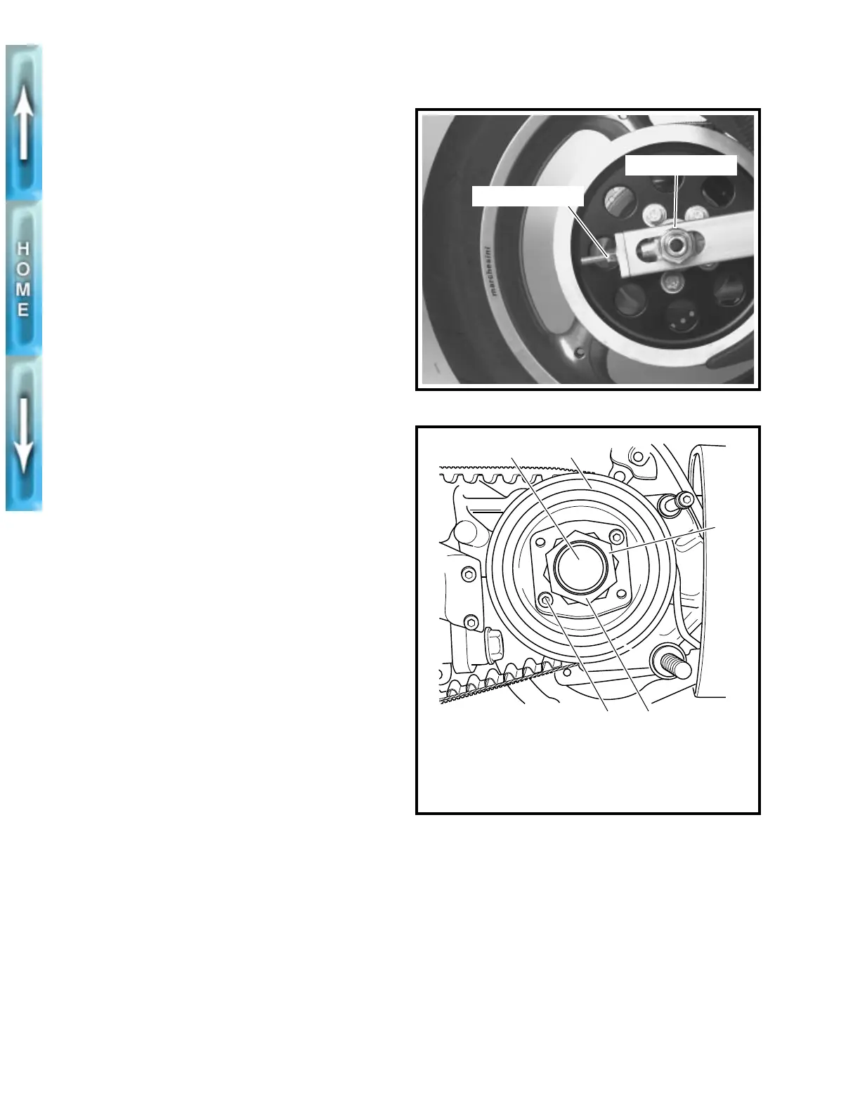
3. See Figure 6-12. Loosen rear axle nut (metric). Reduce
tension on secondary drive belt by turning axle adjuster
nuts on each side of swingarm an equal number of turns
counterclockwise. Move rear wheel as far forward as
possible.
4. Remove muffler. See EXHAUST SYSTEM in Section 2.
Place a drain pan under the engine. Remove drain plug
and drain lubricant from primary drive/transmission.
5. Remove swingarm/drive support screws and retaining
nut. Remove sprocket cover, washer and spacer.
6. See Figure 6-13. Place transmission in first gear.
Remove two socket head screws (5) and lockplate (4).
1CAUTION
Transmission sprocket nut has left-hand threads. To pre-
vent damage, turn nut clockwise to loosen and remove
from main drive gear shaft.
7. Remove transmission sprocket nut (3) from main drive
gear shaft (1).
8. Remove secondary drive belt from transmission sprocket
(2). Remove transmission sprocket from main drive gear
shaft (1).
9. Remove primary cover. See PRIMARY CHAIN on page 6-3.
10. Remove clutch assembly, primary chain and engine
sprocket. See PRIMARY DRIVE/CLUTCH on page 6-10.
11. See Figure 6-14. Lock transmission in gear. Remove
countershaft TORX screw and retainer.
12. See Figure 6-15. Detach spring (1) from groove in
post (2).
13. Remove retaining ring (10) and detent plate (9). You will
need to use a new retaining ring for installation.
14. Remove two locknuts (3) and washers (11) which attach
shifter shaft assembly (6) to studs at transmission case.
Remove shifter shaft assembly.
15. Remove five access door bolts (7) and washers (8).
Remove transmission assembly by pulling it straight out-
ward, away from transmission case.
Figure 6-12. Secondary Drive Belt Adjustment
Figure 6-13. Transmission Sprocket
Axle adjuster nut
Axle nut (metric)
4. Lockplate
5. Socket head
screw (2)
1. Main drive gear shaft
2. Transmission sprocket
3. Transmission sprocket
nut (left hand threads)
1
3
2
45
b0249x6x