2-32
FORK STEM AND BRACKET ASSEMBLY
REMOVAL/DISASSEMBLY
1. Remove fork assemblies. See FRONT FORK, REMOVAL
on page 2-28.
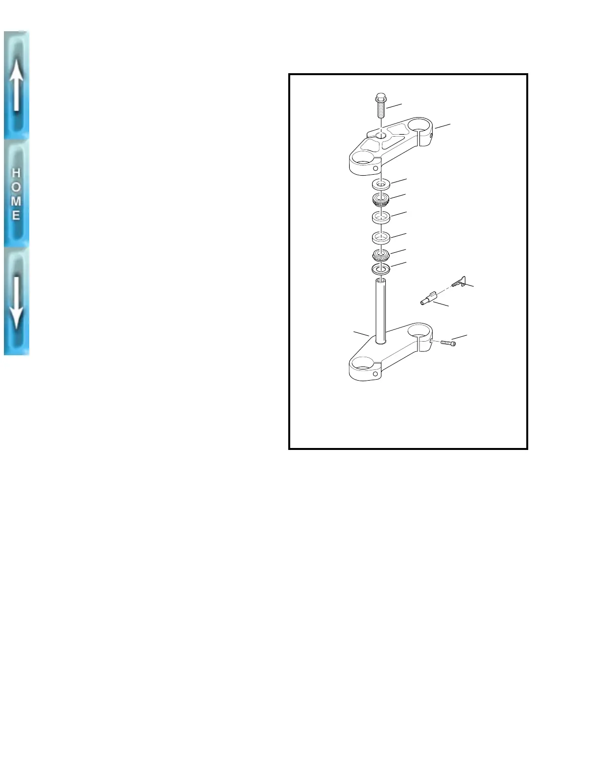
2. See Figure 2-36. Remove fork stem bolt (1) and upper
triple clamp (2).
3. Remove upper dust shield (3) and upper roller
bearing (4).
4. Lower the lower triple clamp (6). The lower bearing cone
is a press fit on fork stem. Chisel through outer bearing
cage to allow rollers to fall free. Apply heat to remove the
remaining portion of bearing cone. Continuously move
flame around its entire circumference until bearing falls
free. Remove lower dust shield (3).
5. If replacement of bearing cups (5) is necessary, drive
cups from steering head using STEERING HEAD BEAR-
ING RACE REMOVER (Part No. HD-39301A) and UNI-
VERSAL DRIVER HANDLE (Part No HD-33416).
CLEANING, INSPECTION AND
REPAIR
See FRONT FORK in Section 1 for adjustment procedures.
1. See Figure 2-36. Clean the dust shields (3), bearing
cups (5), fork stem and lower triple clamp (6) and frame
with solvent.
2. Carefully inspect bearing races and assemblies for pit-
ting, scoring, wear and other damage. Replace damaged
bearing as a set.
3. Check the fork stem and lower triple clamp (6) for dam-
age. Replace damaged fork stem.
ASSEMBLY/INSTALLATION
1. See Figure 2-36. If removed, install
new
bearing cups (5)
into frame steering head using STEERING HEAD BEAR-
ING RACE INSTALLER (Part No. HD-39302).
2. Liberally coat the bearing cones (4) with grease using
WHEEL BEARING PACKER TOOL (Part No. HD-33067).
Work the grease into the rollers.
3. Place lower bearing dust shield (3) over fork stem. Find a
section of pipe having an inside diameter slightly larger
than the outside diameter of the fork stem. Press bearing
cone (4) onto fork stem and bracket (1) using the pipe as
a press on tool.
4. Insert lower triple clamp (6) through the steering head.
Install the upper bracket bearing (4) and dust shield (3)
onto fork stem.
5. Install the upper triple clamp (2) and loosely install fork
stem bolt (11).
6. Install fork assemblies. See FRONT FORK, INSTALLA-
TION on page 2-31.
7. Tighten the fork stem bolt (1) until the bearings have no
freeplay. Make sure the fork stem turns freely, then
tighten the fork stem clamp screw (rearmost pinch screw
on upper triple clamp).
8. Check bearing adjustment. See FRONT FORK,
ADJUSTMENT in Section 1.
Figure 2-36. Bearing Cup Removal
1
2
3
4
5
5
4
3
6
7
9
8
1. Fork stem bolt
2. Upper triple clamp
3. Dust shield (2)
4. Roller bearing (2)
5. Bearing cup (2)
6. Lower triple clamp
7. Screw (5)
8. Steering head lock
9. Steering lock key
b0031a2x