2-28
FRONT FORK
GENERAL
The front fork consists of two telescoping outer tube/inner
slider assemblies. Each tube/slider assembly has an internal
compression spring which supports the forward weight of the
vehicle/rider. The compression spring extends and retracts to
cushion the ride over rough or irregular road surfaces. An oil-
filled damping mechanism controls the telescoping action of
each tube/slider assembly.
See FRONT FORK in Section 1 for fork oil change procedure.
REMOVAL
1. Raise front wheel off floor using FRONT WHEEL SUP-
PORT STAND (Part No. B-41395) and S1 LIFT
ADAPTER (Part No. B-41686).
2. Remove front brake caliper. See FRONT BRAKE CALI-
PER, REMOVAL/DISASSEMBLY on page 2-20.
3. Remove front wheel. See FRONT WHEEL, REMOVAL
on page 2-8.
4. Remove front fender. See FENDERS, REMOVAL/
INSTALLATION on page 2-54.
5. Loosen left and right headlamp brackets. See HEAD-
LAMP, REMOVAL in Section 7.
6. Loosen all five pinch screws on both the upper and lower
triple clamps.
7. Remove front forks.
DISASSEMBLY
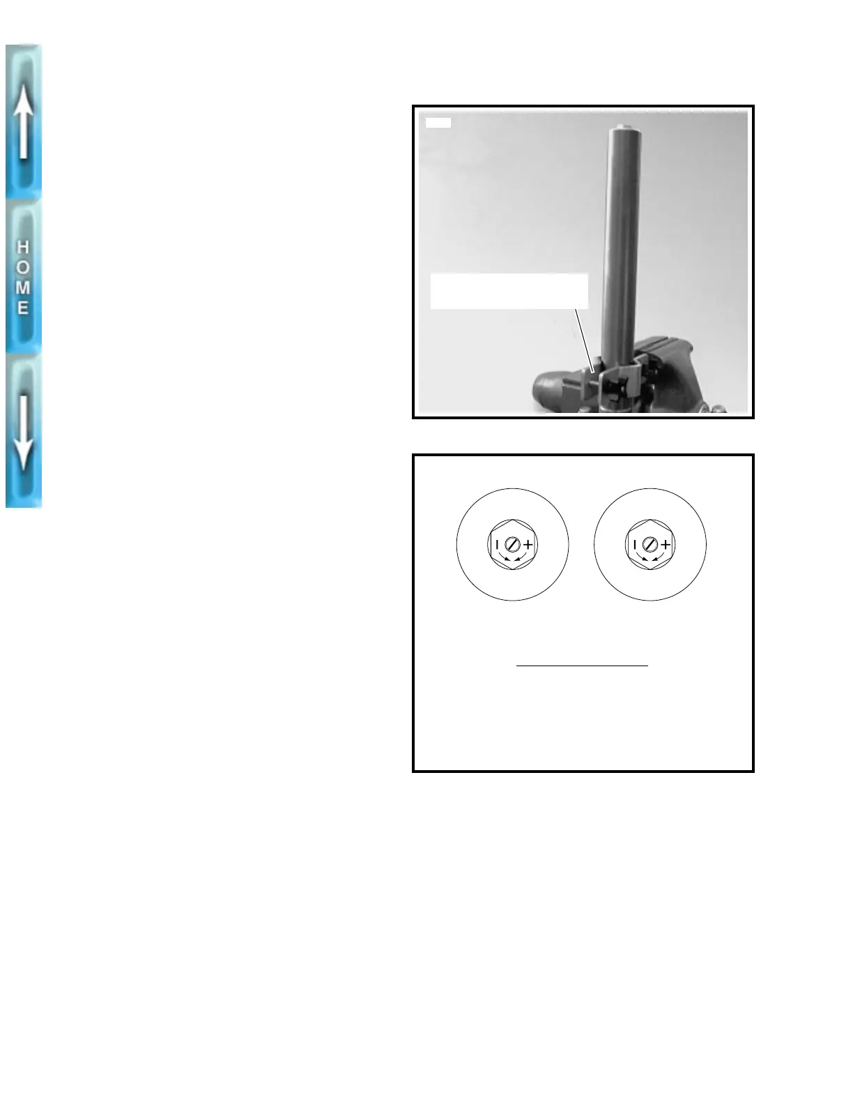
1. See Figure 2-30. Clamp the fork vertically in a vise using
FRONT FORK HOLDING TOOL (Part No. B-41177).
2. See Figure 2-31. Turn adjuster to full slow position (com-
pletely clockwise).
3. See Figure 2-32. Remove fork cap (2) (metric), O-ring (3)
and washer (4).
4. Reduce spring pressure and remove both retaining
clips (5).
5. Remove preload shim(s) (6) and steel washer (7).
6. Remove fork spring (8).
7. Invert fork and drain fork oil.
8. Clamp fork outer tube (9) horizontally using FRONT
FORK HOLDING TOOL (Part No. B-41177). Loosen fork
seal retaining ring (14) and spacer ring (13).
9. Using ROBINAIR HEAT GUN (Part No. HD-25070) heat
bottom of outer tube. When the tube has sufficiently
expanded, drive inner tube (18) from outer tube with a
slide hammer action. Inner tube will retain fork oil seal
(12) and support ring (11) in place.
10. Spread red retaining cap (15) and remove. Remove
upper DU bushing (16) and washer (17).
11. Remove retaining ring (14) and spacer ring (13).
12. Remove lower DU bushing (10), support ring (11) and
fork oil seal (12). Discard fork oil seal and support ring.
13. Invert fork. Hold damper assembly and remove bolt (20)
(metric) and copper washer (19). Discard copper washer.
14. Remove damper assembly (22).
NOTE
The damper assembly (22) contains no user serviceable
parts.
Figure 2-30. Front Fork Holding Tool
Figure 2-31. Fork Adjusters
Front Fork Holding Tool,
(Part No. B-41177)
5761
R
E
B
C
O
M
Right fork leg adjuster-
Compression damping
Left fork leg adjuster-
Rebound damping
b0206x2x
FORK ADJUSTMENTS
Increase
rebound/compression (slower):
Turn appropriate adjuster clockwise.
Decrease
rebound/compression (faster):
Turn appropriate adjuster counterclockwise.
2