2-36
REAR SHOCK ABSORBER
GENERAL
See Figure 2-41. The rear suspension features a WP Suspen-
sion shock absorber. The shock adjusts for compression and
rebound damping as well as spring preload.
The most important rear shock adjustment is the preload set-
ting. Before making any suspension adjustments, set the
proper preload. This procedure can be found under SUSPEN-
SION ADJUSTMENTSon page 2-39.
NOTE
Rear shock absorber contains no user serviceable parts.
REMOVAL
1. Lift rear wheel off ground using REAR WHEEL SUP-
PORT STAND (Part No. B-41174).
2. Remove seat, fuel tank and tail section. See TAIL SEC-
TION, REMOVAL on page 2-55.
3. Support motorcycle frame with a floor hoist such as the
CENTRAL HYDRAULICS FOLDING CRANE.
4. See Figure 2-41. Use a flex socket and extension to
remove allen screw on front reservoir clamp (3).
5. Remove allen screw and locknut (4) (metric) on front
mounting point.
6. Remove allen screw and locknut (1) (metric) on rear
mount while supporting shock absorber.
7. Loosen rear reservoir clamp (2).
8. Remove shock absorber assembly.
DISASSEMBLY
1
WARNING
The following steps require using a press. Wear eye pro-
tection and make certain set-up is stable. The force
involved could cause parts to “flyout” at great speeds
causing personal injury.
1. See Figure 2-42. Place rear shock absorber in a hydrau-
lic press with REAR SHOCK COMPRESSING TOOL
(Part No. B-41178-A) on rear drawing ring.
2. Apply pressure to compress shock spring. Loosen and
remove preload adjusting nuts (metric).
3. Release pressure. Remove REAR SHOCK COM-
PRESSING TOOL (Part No. B-41178-A) and shock from
press.
4. See Figure 2-43. Remove rear drawing ring (2).
5. Remove support ring (3) and bump rubber (4).
6. Remove circlip (5) on end of shock cartridge.
7. Remove steel spring retainer (6).
8. Remove spring (7).
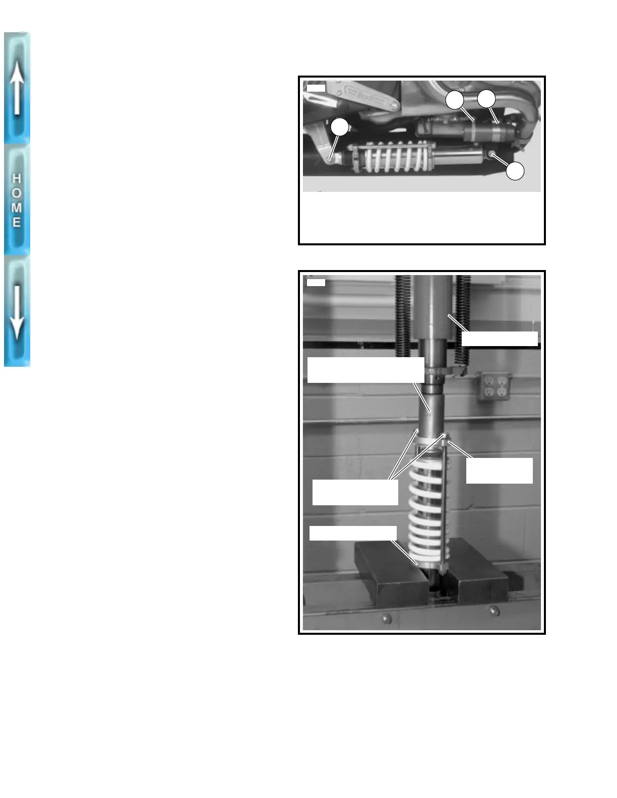
Figure 2-41. Rear Shock Mounting Hardware
Figure 2-42. Compressing Rear Shock
1. Rear allen screw and locknut (metric)
2. Rear reservoir clamp
3. Front reservoir clamp
4. Front allen screw and locknut (metric)
1
2
3
4
5541a
Rear Shock Compressing
Tool (Part No. B-41178-A)
5129a
Preload adjusting
nuts (metric)
Rear drawing
ring
Hydraulic press
Front drawing ring