7-11
IGNITION/HEADLAMP SWITCH
GENERAL
1
WARNING
DO NOT modify the ignition/headlamp switch wiring to
circumvent the automatic-on headlamp feature. Visibility
is a major concern for motorcyclists. Failure to have
proper headlamp operation could lead to personal injury.
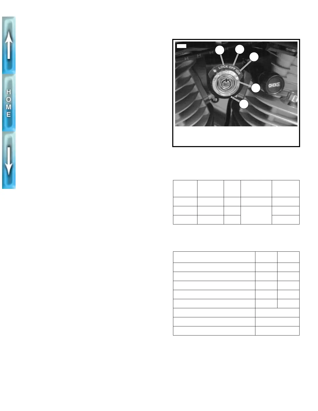
See Figure 7-5. The three-position combination ignition/head-
lamp switch is not repairable. Replace the unit if it fails.
Switch positions are explained in Table 7-1.
1
CAUTION
When turning off the ignition, verify that the key is
removed in the LOCK position or that the lights are not
left on. If the rider stops the engine and inadvertently
removes the key in the OFF position, the battery will be
drained of its charge if the vehicle is left standing too
long.
NOTE
The key locks the ignition system and is removable in both the
LOCK and OFF positions. The OFF position is located
between the LOCK and IGNITION positions and allows the
rider to remove the key while leaving the lights on. When the
key is placed in the OFF position, several indicator markers
are or can be activated. See Table 7-2.
REMOVAL
1. Remove seat and fuel tank. See FUEL TANK, REMOVAL
in Section 4.
1
WARNING
To avoid accidental start-up of vehicle and possible per-
sonal injury, disconnect the battery cables before pro-
ceeding. Always disconnect the negative cable first. If
the positive cable should contact ground with the nega-
tive cable installed, the resulting sparks may cause a bat-
tery explosion producing personal injury.
1
CAUTION
Hold battery cable when loosening battery terminal hard-
ware. Failure to hold cable may cause battery damage.
2. Disconnect battery cables, negative cable first.
3. Cut cable strap securing main wiring harness to frame.
4. See Figure 7-6. Disconnect ignition connector [P8] from
main wiring harness.
5. See Figure 7-5. Remove ignition switch face nut.
6. Remove ignition switch.
Figure 7-5. Ignition/Headlamp Switch
Table 7-1. Ignition Positions
LABEL NAME IGN. LAMPS
REMOVE
KEY
LOCK locked off off yes
OFF markers off See note &
Table 7-2.
yes
IGN ignition on no
Table 7-2. Indicator Markers
ITEM OFF IGN
Headlamp position marker on on
Headlamp high/low beam off on
License plate lamp on on
Speedometer illumination lamp on on
Tachometer illumination lamp off on
Stop lamp can be activated
Front and rear turn signals can be activated
Horn can be activated
1. LOCK position
2. OFF position
3. IGNITION position
4. Switch face nut
5. Ignition switch
bracket
1
5755
2
3
4
5