2-12
DISASSEMBLY
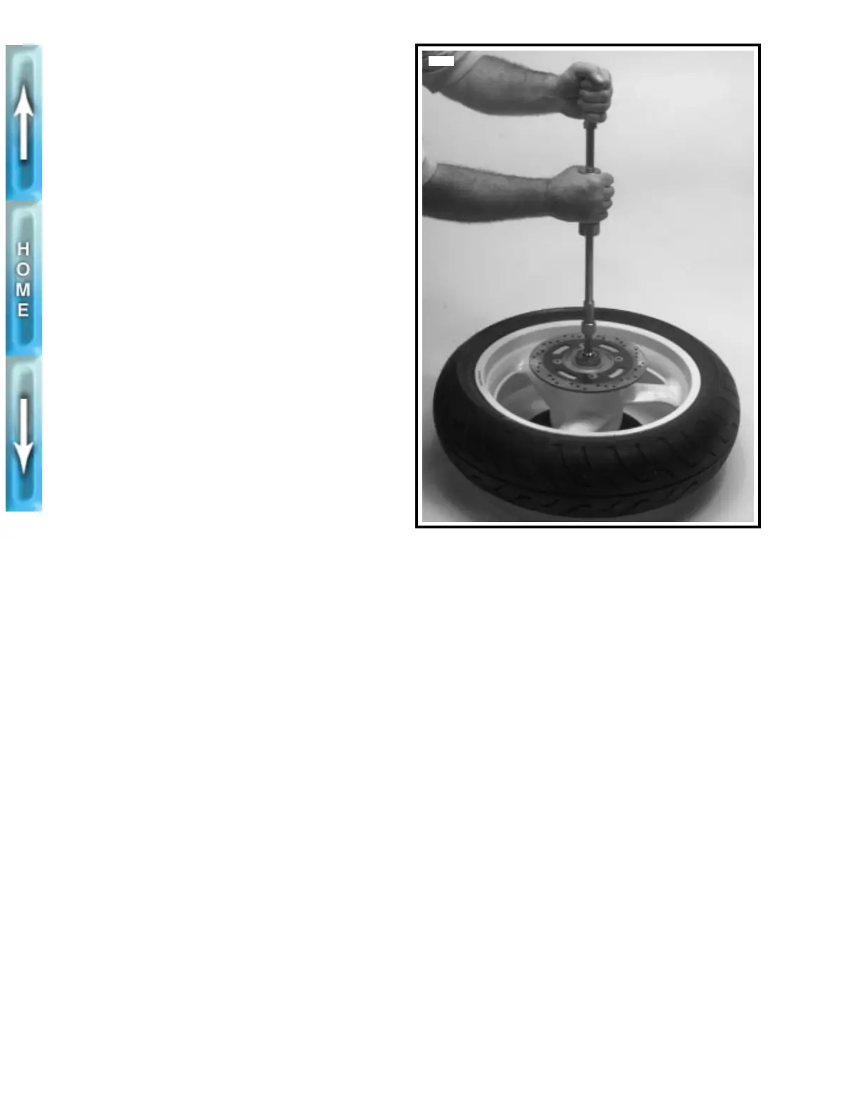
1. See Figure 2-10. Move wheel to bench area. On the
brake rotor side of the wheel, remove bearing using
BUSHING AND BEARING PULLER (Part No. HD-
95760-69A) and 1 1/8 in. COLLET (Part No. HD-95769-
69).
2. Remove two bearings from sprocket side of wheel.
3. See Figure 2-9. Remove four screws (1) (metric) to
remove rear brake rotor (2) from hub.
4. Remove five bolts (17) and washers (16) on belt sprocket
(15). Remove belt sprocket from wheel.
CLEANING, INSPECTION
AND REPAIR
1. Thoroughly clean all parts in solvent.
1
WARNING
Never use compressed air to “spin-dry” bearings. Very
high bearing speeds can damage unlubricated bearings.
Spinning bearings with compressed air can also cause a
bearing to fly apart, which may result in personal injury.
2. Inspect all parts for damage or excessive wear.
3. Inspect brake rotor. Replace rotor if warped or badly
scored. Measure rotor thickness for excessive wear. Min-
imum acceptable thickness (0.19 in. (4.8 mm)) is
stamped on side of rotor.
ASSEMBLY
1
WARNING
Do not allow brake fluid, bearing grease, lubricants, etc.
to contact brake rotor or reduced braking ability will
occur, possibly resulting in personal injury.
1. See Figure 2-9. Verify that brake rotor (2) is thoroughly
clean. Apply LOCTITE THREADLOCKER 242 (blue) to
each screw (1) (metric). Fasten rotor to hub with four
screws. Tighten to 35-40 ft-lbs (47.5-54.2 Nm).
NOTE
P/M wheels use a nut (not shown) with each screw (1).
2. Apply two drops of LOCTITE THREADLOCKER 272
(red) to threads of each sprocket bolt (17). Install belt
sprocket (15) using five bolts (17) and washers (16).
Tighten bolts to 55-65 ft-lbs (74.6-88.1 Nm).
3. On the sprocket side of the wheel, insert two bearings
(10) into hub until they contact shoulder for spacer
sleeve. Press bearings in separately, pressing on outer
race only.
4. Insert spacer sleeve (6) into hub.
5. On the brake rotor side of the wheel, insert bearing (5)
into hub until it contacts end of spacer sleeve. Press on
outer race only.
6. Install tire, if removed. See TIRES, INSTALLATION on
page 2-16.
7. Verify that wheel and tire are true. See CHECKING
CAST RIM RUNOUT on page 2-14.
Figure 2-10. Removing Wheel Bearing Using Bushing/
Bearing Puller (Part No. HD-95760-69A) and
1 1/8 in. Collet (Part No. HD-95769-69)
4878