7-15
2. Remove sprocket cover. See SPROCKET COVER in
Section 2.
3. Cut cable straps holding sensor plate wiring at the follow-
ing locations:
a. Top of starter.
b. Edge of gearcase cover.
c. Oil line.
4. See Figure 7-9. Disconnect sensor plate (8) wiring at
connector (20) [P16] located below the starter motor.
5. Note position of each sensor plate wiring terminal in plug
end of connector (20).
6. Remove terminals. See DEUTSCH ELECTRICAL CON-
NECTORS on page 7-46.
7. Drill off heads of outer timer cover pop rivets (1) using a
3/8 in. (9.525 mm) drill bit. Tap remaining rivet shafts
inboard through holes in timer cover (2) and inner cover
(4). Remove timer cover.
8. Remove inner cover screws (3), inner cover (4) and igni-
tion gasket (5). Carefully remove any remaining pieces of
rivets from gearcase cover timer bore.
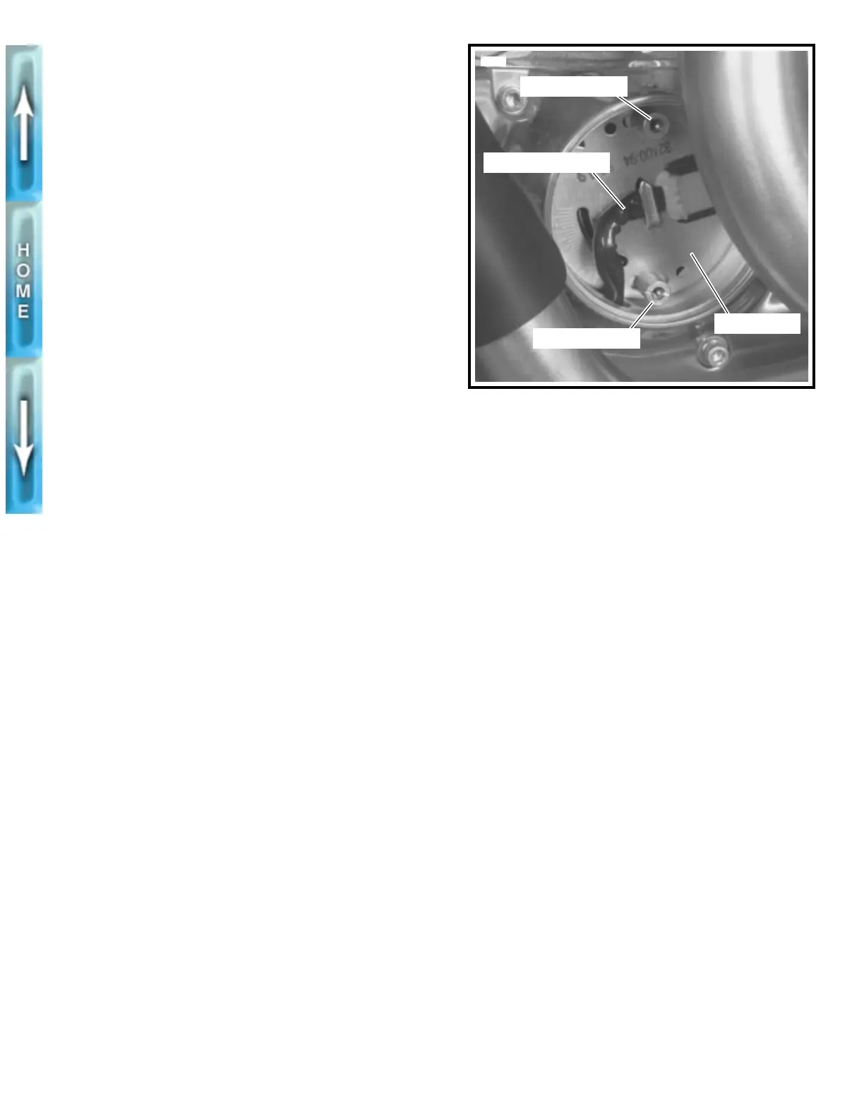
9. See Figure 7-10. To obtain approximate ignition timing
during installation, mark position of timer plate studs on
sensor plate.
10. See Figure 7-9. Remove timer plate studs. Carefully
remove sensor plate. Remove bolt (7) and trigger rotor (9).
11. Carefully remove camshaft oil seal (10) if damaged or if
there is any evidence of oil leakage past the seal.
INSTALLATION
1. See Figure 7-9. With the lipped side facing inboard,
install new camshaft oil seal (10) into gearcase cover
(11), if removed. Press seal into position until flush with
surface of timer bore.
2. Position trigger rotor (9) onto end of camshaft aligning
notch with camshaft slot. Apply LOCTITE THREAD-
LOCKER 242 (blue) to bolt (7). Install bolt to secure
rotor. Tighten bolt to 75-80 in-lbs (8.5-9.0 Nm).
3. Install sensor plate (8) and timer plate studs (6). Rotate
sensor plate to its previously marked position to obtain
approximate ignition timing.
1CAUTION
Route sensor plate wires about 1-1/2 in. (38 mm) forward
of gearcase cover rear edge. If wires are routed too far to
the rear of this position, they could contact the moving
secondary drive belt and/or sprocket resulting in damage
to sensor plate wiring.
4. Route sensor plate wiring leads.
a. Downward through hole (7 o’clock position) in timer
bore of gearcase cover (11).
b. Upward through bottom opening between right
crankcase half and rear of gearcase cover.
c. Route wiring around tower shaft behind gearcase
cover. Route wires upward to starter motor.
d. Cable strap sensor plate wiring. See Step 3 of
REMOVAL.
5. Install sensor plate wiring terminals into correct positions
in plug end of connector (20) [P16]. Red, green and black
wires of plug end (from sensor plate) must match same
color wires in receptacle end of connector (from ignition
module wiring harness). See Figure 7-4. Install terminals
following procedure outlined under DEUTSCH ELECTRI-
CAL CONNECTORS on page 7-46.
6. Connect sensor plate (8) wiring to wiring harness con-
nector (20) [P16].
7. Check ignition timing. See IGNITION TIMING in Section 1.
8. Final tighten timer plate studs (6) to 12-20 in-lbs (1.4-2.3
Nm).
9. Install gasket (5) and inner cover (4) using screws (3).
Tighten screws to 12-20 in-lbs (1.4-2.3 Nm).
1CAUTION
Use only H-D Part No. 8699 rivets to secure outer timing
cover. These rivets are specially designed so that no rivet
end falls off into the timing compartment. Use of regular
rivets can damage ignition system components and may
allow water to enter the timing compartment.
10. Secure timer cover (2) to inner cover using new rivets.
1WARNING
Always connect the positive battery cable first. If the pos-
itive cable should contact ground with the negative cable
installed, the resulting sparks may cause a battery explo-
sion producing personal injury.
1CAUTION
Hold battery cable when tightening battery terminal hard-
ware. Failure to hold cable may cause battery damage.
11. Install battery cables, positive cable first.
Figure 7-10. Marking Ignition Timing
5630
Timer plate stud
Timer plate stud
Sensor plate wiring
Sensor plate