7-13
IGNITION MODULE
GENERAL
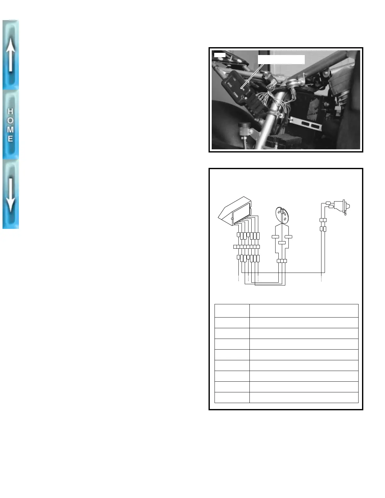
See Figure 7-7. The ignition module is located on a plate
which is a portion of the frame. The ignition module is not
repairable. Replace the unit if it fails.
See IGNITION SYSTEM on page 7-3 for information on the
function and testing of the ignition module.
REMOVAL
1. Remove seat and tail section. See TAIL SECTION,
REMOVAL in Section 2.
1
WARNING
To avoid accidental start-up of vehicle and possible per-
sonal injury, disconnect the battery cables before pro-
ceeding. Always disconnect the negative cable first. If
the positive cable should contact ground with the nega-
tive cable installed, the resulting sparks may cause a bat-
tery explosion producing personal injury.
1
CAUTION
Hold battery cable when loosening battery terminal hard-
ware. Failure to hold cable may cause battery damage.
2. Disconnect battery cables, negative cable first.
3. Cut cable strap which secures main wire harness to side
frame member.
4. See Figure 7-8. Disconnect ignition module connector
[P10] from main wiring harness.
5. See Figure 7-7. Remove screws and washers to detach
module from frame.
INSTALLATION
1. See Figure 7-7. Fasten module to frame using screws
and washers.
2. See Figure 7-8. Attach ignition module connector [P10]
to main wiring harness.
3. Secure main wiring harness to frame member with a
new
cable strap.
1
WARNING
Always connect the positive battery cable first. If the pos-
itive cable should contact ground with the negative cable
installed, the resulting sparks may cause a battery explo-
sion producing personal injury and
/
or property damage.
1
CAUTION
Hold battery cable when tightening battery terminal hard-
ware. Failure to hold cable may cause battery damage.
4. Install battery cables, positive cable first.
1
WARNING
After installing seat, pull upward on front of seat to be
sure it is locked in position. If seat is loose, it could shift
during vehicle operation and startle the rider, causing
loss of control and personal injury.
5. Install tail section and seat. See TAIL SECTION, INSTAL-
LATION in Section 2.
6. Test engine for proper ignition system operation.
Figure 7-7. Ignition Module
Figure 7-8. Ignition Module Connector [P10]
5682
Ignition module
b0225x7x
[P10] WIRE TERMINATION
1 Splice number eight
2 Timer and pickup
3 Timer and pickup
4 Coil
5 Timer and pickup
6 Vacuum-operated switch
7 Splice number two
8 Empty
P10
ELECTRONIC
IGNITION MODULE
TIMER
AND PICKUP
BK
PK
BK/W
GN/W
W/BK
R/W
V/W
12345678
BK
PK
BK/W
GN/W
W/BK
R/W
V/W
P16
/WGN
/WBK
CB
A
R/W
P7
BK
BK
21
KB
/WV
VACUUM
SWITCH