3-49
6. Remove starter motor as described under STARTER,
REMOVAL in Section 5.
7. Remove transmission. See TRANSMISSION CASE in
Section 6.
8. See Figure 3-65. Remove screws (2) and rear engine
mount bolt securing crankcase halves together.
9. Position crankcase on work bench, gearcase side up.
Tap crankcase with plastic mallet to loosen top half and
separate the halves.
1
WARNING
The following step requires using a press. Wear eye pro-
tection and make certain set-up is stable. The force
involved could cause parts to “fly out” and cause per-
sonal injury.
10. See Figure 3-66. Mount the left case half and flywheel
assembly on a press table, supporting crankcase on par-
allel bars. Press on end of sprocket shaft with arbor
press until flywheel assembly is free from case half. Do
not drive flywheel assembly from case half as flywheels
may be knocked out of alignment.
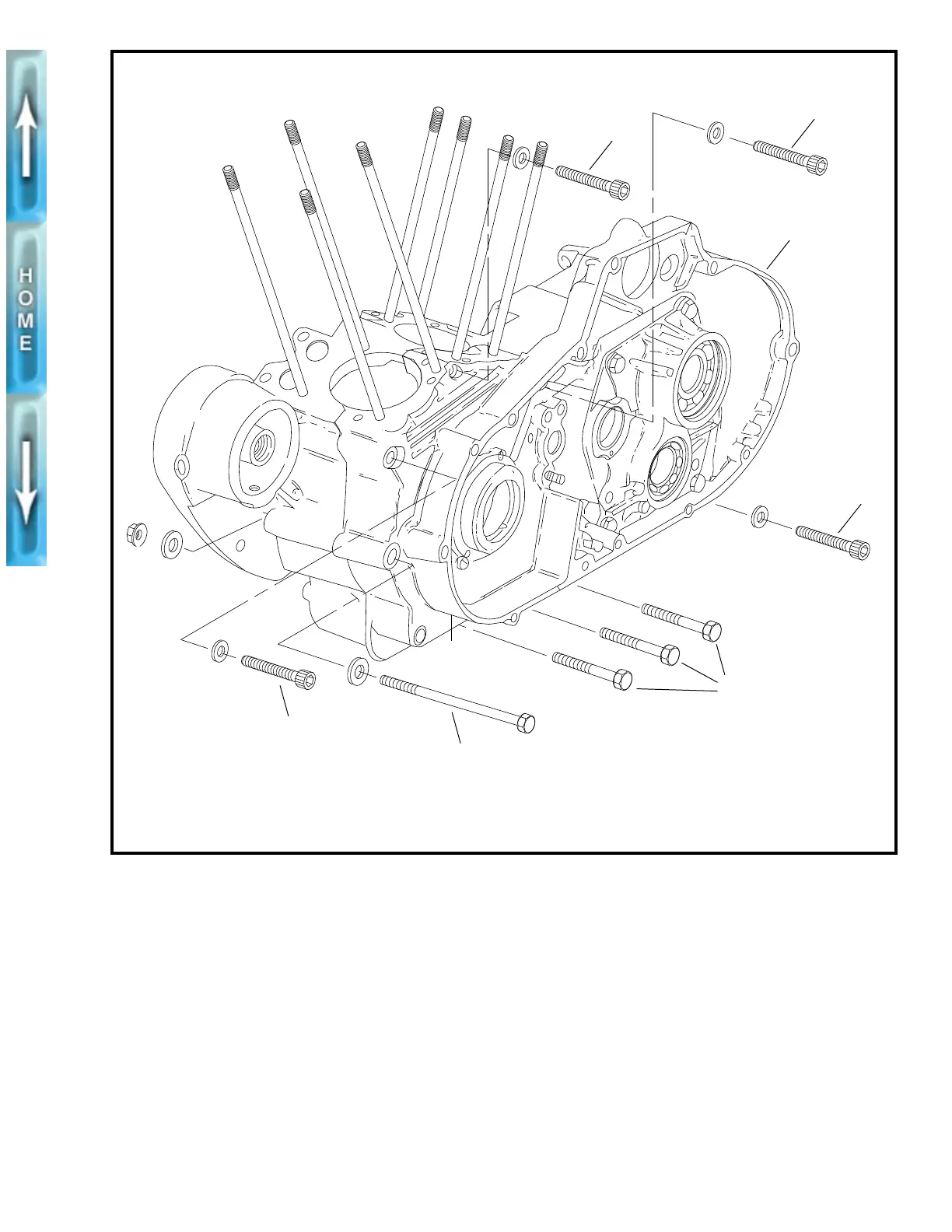
Figure 3-65. Crankcase Hardware
1. Crankcase
2. Upper case hex socket head screw – 5/16-18 X 2-1/2 in. long (4)
3. Bottom case hex head bolt – 1/4-20 X 3/4 in. long (3)
4. Muffler mount bolt – 3/8-16 X 5-1/2 in. long (2, with washers and locknuts)
b0069a3x
2
2
1
2
3
2
4