3-48
CRANKCASE
GENERAL
When rod bearings, pinion shaft bearing or sprocket shaft
bearing are in need of repair, the engine must be removed
from the chassis. See REMOVING ENGINE CRANKCASE
OR COMPLETE ENGINE on page 3-8. It is recommended
procedure to check and make repairs to cylinder heads, cylin-
ders, gearcase and transmission at the same time (perform
entire engine overhaul).
1
CAUTION
If engine is removed from chassis, do not lay engine on
primary side. Placing engine on primary side will damage
clutch cable end fitting. If fitting is damaged, clutch cable
must be replaced.
ADJUSTMENT/TESTING
Flywheel End Play
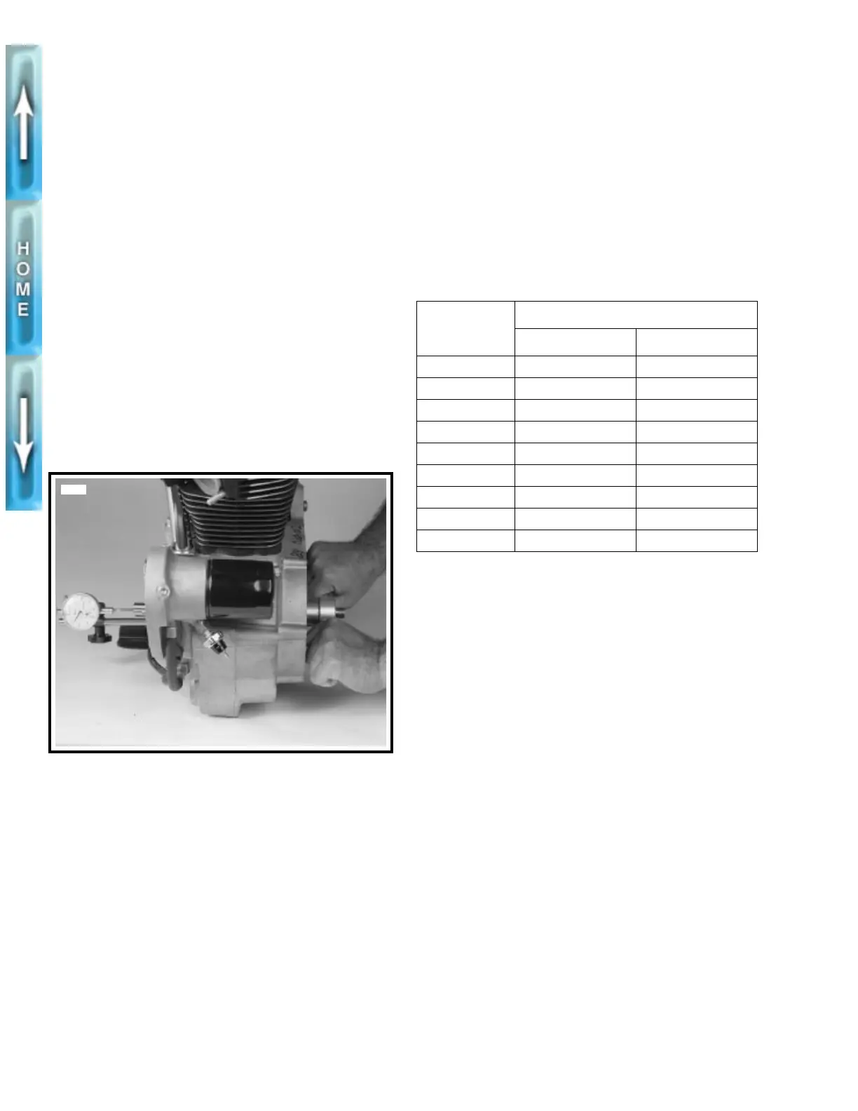
See Figure 3-64. Before completely disassembling crank-
cases, check flywheel end play.
1. After engine has been removed from chassis, securely
fasten it to a stand or workbench.
2. Remove gearcase cover. Attach a dial indicator to gear
side crankcase with indicator stem on end of gearshaft.
3. Sprocket shaft bearings must be preloaded to obtain an
accurate flywheel end play reading. A suitable tool can
be made by welding two handles to an old sprocket shaft
nut. Install the nut and sprocket. Tighten nut to 150-
165 ft-lbs (203-224 Nm).
4. Rotate and push on sprocket shaft while reading dial
indicator. Then rotate and pull on sprocket shaft while
reading dial indicator. If difference (end play) in indicator
readings is not 0.001-0.005 in. (0.025-0.13 mm), bearing
inner spacer (shim) (item 6, Figure 3-68.) must be
replaced. Choose spacer from Table 3-11. Use a thinner
spacer for less end play; use a thicker spacer for more
end play.
DISASSEMBLY
Crankcase Halves
1. Remove cylinder heads as described under CYLINDER
HEAD, REMOVAL on page 3-11.
1
CAUTION
After removing cylinders, install plastic or rubber hose
over cylinder studs. Lifting or moving crankcase by
grasping studs will cause cylinder stud damage.
2. Remove cylinders and pistons. See CYLINDER AND
PISTON, REMOVAL/DISASSEMBLY on page 3-22.
3. Remove oil pump as described under OIL PUMP,
REMOVAL/DISASSEMBLY on page 3-35.
4. Remove gearcase components. See GEARCASE
COVER AND CAM GEARS, REMOVAL/DISASSEMBLY
on page 3-40.
5. Remove clutch and primary drive components. See PRI-
MARY DRIVE/CLUTCH in Section 6.
Figure 3-64. Checking Flywheel End Play
3536a
Table 3-11. Flywheel End Play
Spacers (Shims)
PART
NUMBER
THICKNESS
IN. MM
9155 0.0975-0.0985 2.476-2.502
9142 0.0995 - 0.1005 2.527-2.553
9143 0.1015-0.1025 2.578-2.603
9144 0.1035 - 0.1045 2.629-2.654
9145 0.1055 - 0.1065 2.680-2.705
9146 0.1075 - 0.1085 2.730-2.756
9147 0.1095 - 0.1105 2.781-2.807
9148 0.1115 - 0.1125 2.832-2.857
9149 0.1135 - 0.1145 2.883-2.908
 Loading...


