6-26
MAIN DRIVE GEAR
REMOVAL
1. Remove transmission. See TRANSMISSION CASE,
REMOVAL on page 6-16.
2. See Figure 6-35. From inside case tap out seal (3) at end
of mainshaft 5th gear (1). Discard seal (3).
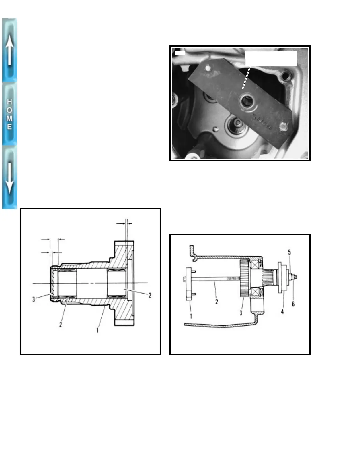
3. See Figure 6-36. Use MAIN DRIVE GEAR REMOVER
AND INSTALLER (Part No. HD-35316-A) with CROSS
PLATE (Part No. HD-35316-91). Take support bracket (1)
and insert pins, at one side, into holes which are now
exposed under access cover.
4. See Figure 6-37. Insert bolt (2) through support bracket
(1) and 5th gear (3).
1
CAUTION
When removing the main drive gear, the gear is pressed
out against the resistance of the bearing inner race. With-
out any support at the inner race, the bearing is
destroyed. Whenever the main drive gear is removed the
main drive gear bearing will also have to be replaced.
5. At outside of case, place driver (4) and thrust washer (5)
over end of bolt (2). Install and tighten nut (6) until 5th
gear (3) is free.
Figure 6-35. Main Drive Gear Assembly
1. Main drive gear
2. Needle bearing
3. Seal
For outer bearing
For seal
0.080 in.
(2.03 mm)
0.315-0.285 in.
(8.001-7.239 mm)
0.06-0.03 in.
(1.5-0.7 mm)
For inner bearing
xlh0639
Figure 6-36. Support Bracket Mounting
Figure 6-37. Removing Main Drive Gear
Cross Plate (Part
No. HD-35316-91)
3563
1. Support bracket
2. Bolt
3. 5th gear
4. Driver
5. Thrust washer
6. Nut
xlh0641