2-43
THROTTLE CONTROL
REMOVAL/DISASSEMBLY
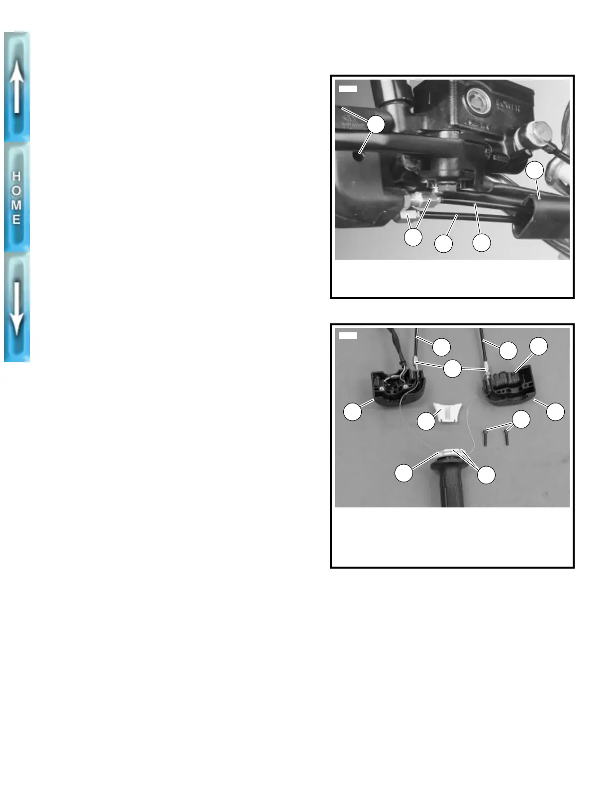
1. See Figure 2-50. Slide rubber boot (5) off the cable
adjusters (2). Loosen jam nut (metric) on each adjuster.
2. Remove two screws (1) (metric). Separate housings from
handlebar.
3. See Figure 2-51. Unhook ferrules (7) from cable wheel (8).
4. Remove cables from under cable guide (6).
5. Remove cables from housings (5, 9) by loosening cable
adjusters (2) (metric).
6. Remove air cleaner assembly. See AIR CLEANER,
REMOVAL in Section 4.
7. Disconnect cables from carburetor.
8. Remove cables from motorcycle.
CLEANING, INSPECTION
AND REPAIR
Clean all parts in a non-flammable cleaning solvent. Blow dry
with compressed air. Replace cables if frayed, kinked or bent.
ASSEMBLY/INSTALLATION
1. See Figure 2-51. Screw cable assemblies (3, 4) into
housings (5, 9). Throttle control cable (4) has a larger fit-
ting end and is positioned inside the front housing (5).
Idle control cable (3) has a smaller fitting end and is posi-
tioned inside the rear housing (9).
2. Run cables in grooves on cable guide (6).
3. Attach ferrules (7) to cable wheel (8). When properly
assembled, notches for ferrules will be at 12 o’clock.
4. Position housings on right handlebar by engaging locat-
ing pin (10) on front housing with hole in handlebar.
Attach housings with screws (1) (metric). Tighten to 12-
17 in-lbs (1.4-1.9 Nm).
5. Route idle and throttle control cables.
a. Cables must be routed forward from throttle control
grip, forward of upper triple clamp and down and to
the left.
b. Continue between side of frame steering head and
left frame tube. Cables should be above and to the
left of the D-shaped washer behind the steering
head.
c. Route cables below the fuel tank and above the horn
mount. Continue downward to carburetor.
6. Install idle control cable into longer, inboard cable guide
on carburetor.
7. Install throttle control cable into shorter, outboard cable
guide on carburetor.
8. Adjust throttle cables. See CARBURETOR, CABLE
ADJUSTMENT in Section 1.
9. Install air cleaner. See AIR CLEANER, INSTALLATION
in Section 4.
Figure 2-50. Throttle Control Cables
Figure 2-51. Cable Connections
1. Screws (2) (metric)
2. Cable adjusters (2)
3. Idle control cable
5587
3
4
2
5
1
4. Throttle control cable
5. Rubber boot
1. Screws (2) (metric)
2. Cable adjusters (2)
3. Idle control cable
4. Throttle control cable
5. Front housing
5719
6. Cable guide
7. Ferrules
8. Cable wheel
9. Rear housing
10. Locating pin
3
4
6
8
7
9 5
2
1
10