7-12
INSTALLATION
1. Insert ignition switch into hole of switch bracket. The
word “TOP” stamped on the switch body should face
upward toward the lettering on the switch position decal.
Loosely install face nut.
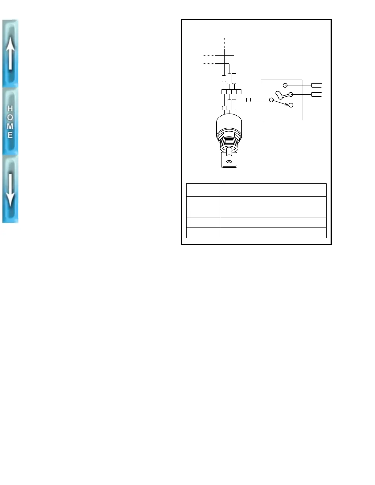
2. See Figure 7-6. Attach ignition switch connector [P8] to
main wiring harness.
3. Tighten face nut to secure switch within cover.
4. Secure main wiring harness to frame with a
new
cable
strap.
1
WARNING
Always connect the positive battery cable first. If the pos-
itive cable should contact ground with the negative cable
installed, the resulting sparks may cause a battery explo-
sion producing personal injury.
1
CAUTION
Hold battery cable when tightening battery terminal hard-
ware. Failure to hold cable may cause battery damage.
5. Install battery cables, positive cable first.
6. Install fuel tank and seat. See FUEL TANK, INSTALLA-
TION in Section 4.
1
WARNING
Check for proper headlamp operation before riding
motorcycle. Visibility is a major concern for motorcy-
clists. Failure to have proper headlamp operation could
lead to personal injury.
7. Check ignition/headlamp switch for proper operation.
Figure 7-6. Ignition Switch Connector [P8]
A
B
C
D
P8
/RGY
/RGY
/BRK
R
/BR
R
K
R
/BRK
/RGY
KEY SWITCH
LOCK
OFF
IGN
[P8] WIRE TERMINATION
A Master circuit breaker
B Accessories fuse in fuse block
C Ignition fuse in fuse block
D Empty
b0226x7x