7-40
Left Side
1. Attach switch housing to handlebar with three screws
(metric). Tighten screws to 25-33 in-lbs (2.8-3.7 Nm).
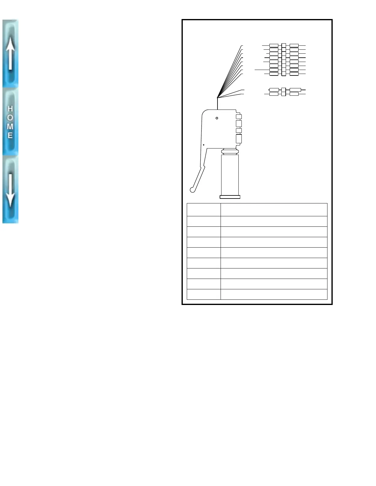
2. See Figure 7-41. Route switch housing wiring harness
between front forks and along right side frame tube.
Attach connector [P6] to wiring harness. Fasten wiring
harness to frame with new cable straps.
3. Install fuel tank and seat. See FUEL TANK, INSTALLA-
TION in Section 4.
1WARNING
Check all handlebar switch operations before riding
motorcycle. Handlebar switches not operating properly
could lead to personal injury.
4. Check handlebar switch for proper operation.
Figure 7-41. Left Handlebar Switch Connection [P6]
BK
1
2
BK
TN/GN
R/BE
P6
P5
CLUTCH SWITCH
LEFT HANDLEBAR
SWITCH CONNECTOR
LOW BEAM
HIGH BEAM
RIGHT TURN
LIGHT POWER
LEFT TURN
FROM FLASHER
HORN POWER
HORN
TO GROUND
FROM IGN RLY
1
3
4
5
6
7
8
2
W
Y
O/W
Y/BK
V
BN
BE
W
BK
BN
LT.B E
O
BE
GN
GY
V/BN
[P6] WIRE TERMINATION
1 Headlamp connector [P4]
2 Splice number nine
3 Splice number three
4 Splice number four
5 Splice number five
6 Turn signal flasher
7 Horn
8 Splice number six