6-28
ACCESS DOOR BEARINGS
REMOVAL
Mainshaft and Countershaft Bearings
1. Remove transmission assembly. See TRANSMISSION
CASE, REMOVAL on page 6-16. Remove shifter forks
and drum as described under SHIFTER FORKS AND
DRUM on page 6-18. Remove countershaft and main-
shaft. See MAINSHAFT AND COUNTERSHAFT starting
on page 6-20.
2. Inspect the mainshaft and countershaft ball bearings for
pitting, scoring, discoloration or other damage.
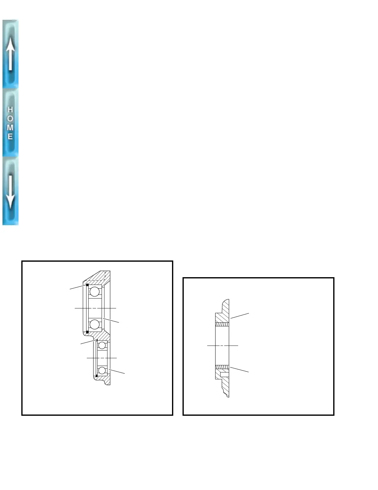
3. See Figure 6-40. If bearing replacement is required,
remove retaining rings (1, 2). Press out bearings (3, 4)
from the inside of the door.
Shift Drum Bushing
1. Inspect the shifter drum bushing for pitting, scoring, dis-
coloration or excessive wear. If bushing requires replace-
ment press bushing out of door from either side.
INSTALLATION
Mainshaft and Countershaft Bearings
1. Lay access door on press with inside surface of door
downward.
2. Lay bearing squarely over bore with printed side of bear-
ing upward. Place section of pipe or tubing (slightly
smaller than outside diameter of bearing) against outer
race. Press bearing into bore until bearing bottoms
against shoulder.
3. Install
new
retaining ring with beveled side facing away
from bearing.
Shift Drum Bushing
1. Lay access door on press with outside surface of door
downward.
2. See Figure 6-41. Lay bushing squarely over bore. Locate
socket or pipe that is slightly larger than diameter of
bushing. Place socket or pipe on bushing and press into
bore until bushing is flush with or 0.020 in. (0.51 mm)
below inside surface. If using a pressing tool larger than
diameter of bushing, the pressing tool will bottom against
door when bushing is flush with top surface.
Figure 6-40. Ball Bearing Assembly
1. Retaining ring
2. Retaining ring
3. Bearing, mainshaft
4. Bearing, countershaft
b0181x6x
1
2
3
4
Figure 6-41. Shift Drum Bushing Assembly
Assemble bushing flush
to 0.020 in. (0.51 mm)
recess from this surface
Shift drum bushing
b0182x6x