7-39
HANDLEBAR SWITCHES
REMOVAL
NOTE
The individual handlebar switches are not repairable. Replace
the switch assembly upon switch failure.
Right Side
1. See Steps 1-5 of THROTTLE CONTROL, REMOVAL/
DISASSEMBLY in Section 2.
2. Remove seat and fuel tank. See FUEL TANK, REMOVAL
in Section 4.
3. See Figure 7-40. Cut as many cable straps as necessary
to access right handlebar switch connector [P1] along
right side frame tube. Detach connector [P1] from wiring
harness.
Left Side
1. Remove three screws (metric) from handlebar switch.
2. Separate switch housings and remove from handlebar.
3. Remove seat and fuel tank. See FUEL TANK, REMOVAL
in Section 4.
4. See Figure 7-41. Cut as many cable straps as necessary
to access left handlebar switch connector [P6] along right
side frame tube. Detach connector [P6] from wiring har-
ness.
INSTALLATION
Right Side
1. See Steps 1-3 of THROTTLE CONTROL, ASSEMBLY/
INSTALLATION in Section 2.
2. Position housings on right handlebar by engaging stud
on front housing with hole in handlebar. Fasten housings
with two screws (metric). Tighten to 12-17 in-lbs (1.4-
1.9 Nm).
3. See Figure 7-40. Route switch housing wiring harness
between front forks and along right side frame tube.
Attach connector [P1] to wiring harness. Fasten wiring
harness to frame with new cable straps.
4. Install fuel tank and seat. See FUEL TANK, INSTALLA-
TION in Section 4.
5. Adjust throttle cables as described under CARBURE-
TOR, CABLE ADJUSTMENT in Section 1.
1WARNING
Check all handlebar switch operations before riding
motorcycle. Handlebar switches not operating properly
could lead to personal injury.
6. Check handlebar switch for proper operation.
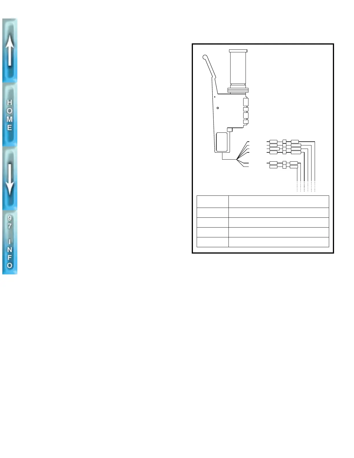
Figure 7-40. Right Handlebar Switch Connection [P1]
GY
W/BK
W/BK
BK/R
4
2
3
1
GN/BK
W/R
BE
Y/O
P1
P2
BRAKE SWITCH
RIGHT HANDLEBAR
SWITCH CONNECTOR
1
2
O/WO/W
R/YR/Y
TO STOPLIGHT
ACC POWER
IGN MODULE
FROM (2)
TO STARTER
IGN POWER
[P11] WIRE TERMINATION
1 Ignition relay [P12]
2 Splice number eight
3 Splice number eight
4 Starter relay [P13]
b0235x7x