7-29
ALTERNATOR
REMOVAL/DISASSEMBLY
1
WARNING
To avoid accidental start-up of vehicle and possible per-
sonal injury, disconnect the battery cables before pro-
ceeding. Always disconnect the negative cable first. If
the positive cable should contact ground with the nega-
tive cable installed, the resulting sparks may cause a bat-
tery explosion producing personal injury.
1
CAUTION
Hold battery cable when loosening battery terminal hard-
ware. Failure to hold cable may cause battery damage.
1. Disconnect battery cables, negative cable first.
2. Remove primary cover. See PRIMARY CHAIN in Section 6.
3. Remove clutch assembly, primary chain and engine
sprocket/rotor assembly as a unit. Refer to PRIMARY
DRIVE/CLUTCH in Section 6. Remove/disassemble
rotor and/or stator, as required. Refer to the following
procedures.
Rotor
1. Remove bolts which secure alternator rotor to engine
sprocket.
2. See Figure 7-26. Position blocking under rotor. Press
sprocket free of rotor.
NOTE
Resistance to sprocket/rotor disassembly is due in part to the
magnetic force of the permanent rotor magnets.
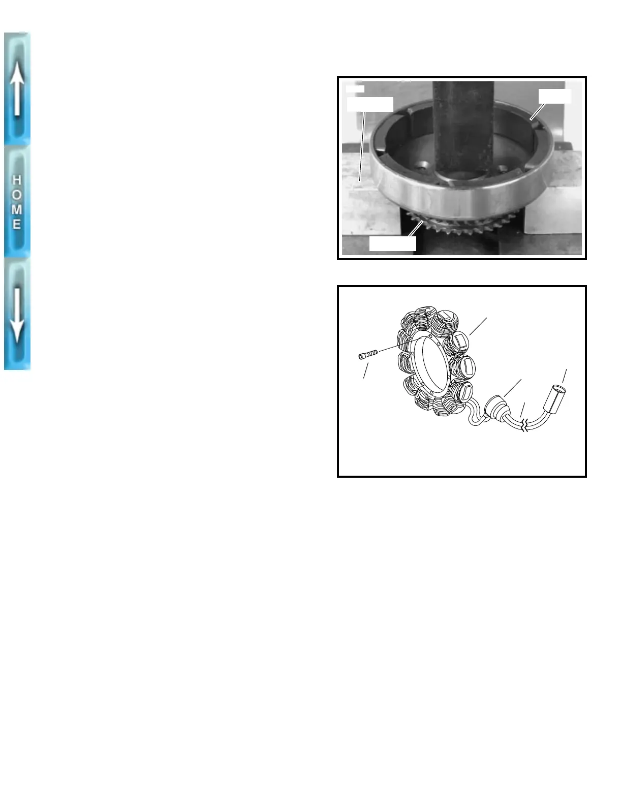
Stator
1. See Figure 7-27. Disconnect stator wiring (4) from volt-
age regulator wiring at connector (5) [P17].
2. Remove cable straps holding stator wire to frame.
3. Withdraw stator wiring (4) from below starter.
4. Remove and discard the four Torx screws (2) which
secure stator (1) to left crankcase half.
1
CAUTION
Stator TORX screws contain a thread locking compound.
Do not reuse existing screws. Always use new screws
with the proper thread locking compound. Loss of torque
on TORX fasteners could result in alternator damage.
5. Remove stator wiring grommet (3) from left crankcase
half.
6. Withdraw stator wiring (4) from grommet hole in left
crankcase half. Remove stator (1).
Figure 7-26. Removing Rotor From Sprocket
Figure 7-27. Stator Assembly
Sprocket
3558
Rotor
Blocking
1. Stator
2. Torx screw (4)
3. Grommet
4. Stator wiring
5. Connector [P17]
b0082x7x
1
3
5
4
2