6-20
MAINSHAFT AND COUNTERSHAFT
DISASSEMBLY
1. Remove transmission assembly. See TRANSMISSION
CASE, REMOVAL on page 6-16. Remove shifter forks
and drum as described under SHIFTER FORKS AND
DRUM on page 6-18.
2. See Figure 6-20. Clamp transmission assembly in vise,
with protective jaws, as shown, to work on disassembly.
NOTE
As the transmission runs, each part develops a certain wear
pattern and a kind of “set” with its mating parts. For this rea-
son, it is important that each component be reinstalled in its
original location and facing its original direction.
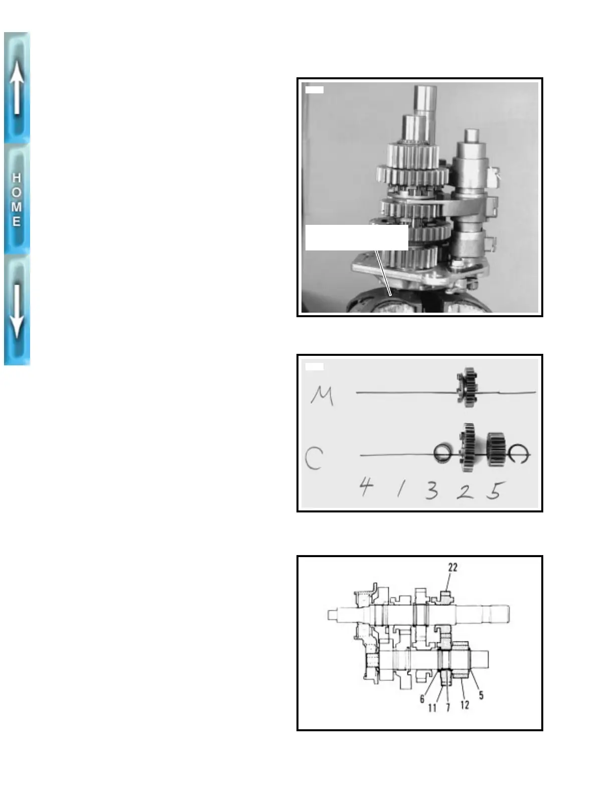
3. See Figure 6-21. As each component is removed, place
it on a clean surface in the exact order of removal.
See Figure 6-22. Using RETAINING RING PLIERS (Part No.
J-5586) remove and discard retaining ring (5) next to counter-
shaft 5th gear (12). Slide countershaft 5th (12), mainshaft 2nd
(22) and countershaft 2nd (11) off end of shafts. Remove split
bearing (7) that was under gear (11) and thrust washer (6) on
the countershaft.
Figure 6-20.
Figure 6-21.
Figure 6-22.
3552
Use protective jaws
when clamping in vise
3559
xlh0626
6