EasyManuals Logo

Buell S1 Lightning User Manual

Buell S1 Lightning
371 pages
To Next Page IconTo Next Page
To Previous Page IconTo Previous Page
Page #168 background imageLoading...
Page #168 background image
3-32
CRANKCASE BREATHING SYSTEM
GENERAL
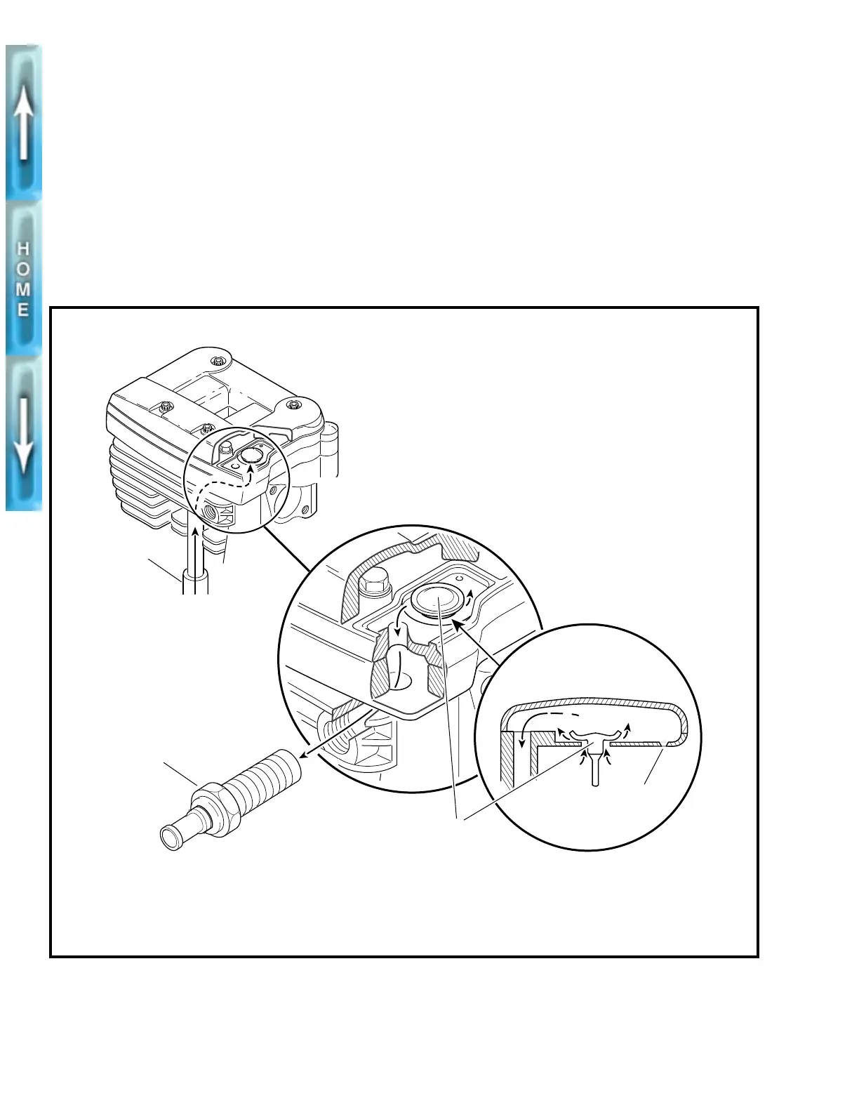
See Figure 3-43. On piston downstroke, a mixture of crankcase
air and oil mist is vented up the push rod covers (1) through an
umbrella valve (3) in each middle rocker box section. The oil
mist separates from the crankcase air, collects and passes
through a small drain hole (2) where it eventually returns to the
crankcase. The crankcase air is routed through a passage in
each cylinder head. The crankcase air then travels through
each air cleaner breather bolt (4) into a hose leading into the
air cleaner.
Figure 3-43. Crankcase Breathing System – Typical Cylinder
1. Push rod cover (2)
2. Oil drain hole
3. Umbrella valve
4. Breather bolt
b0143a3x
1
4
3
2

Table of Contents

Questions and Answers:

Question and Answer IconNeed help?

Do you have a question about the Buell S1 Lightning and is the answer not in the manual?

Buell S1 Lightning Specifications

General IconGeneral
Transmission5-speed
Rear BrakesSingle 230mm disc, single-piston caliper
Compression Ratio10.0:1
IgnitionElectronic
Engine TypeAir-cooled, four-stroke, 45° V-twin
Rear SuspensionShowa monoshock, adjustable preload, compression and rebound damping
Front BrakesSingle 340mm disc, 6-piston caliper
Seat Height775 mm
Bore x Stroke88.8 mm x 96.8 mm
Fuel SystemCarburetor
FrameTubular steel
TiresFront: 120/70 ZR17, Rear: 170/60 ZR17

Related product manuals