3-13
.
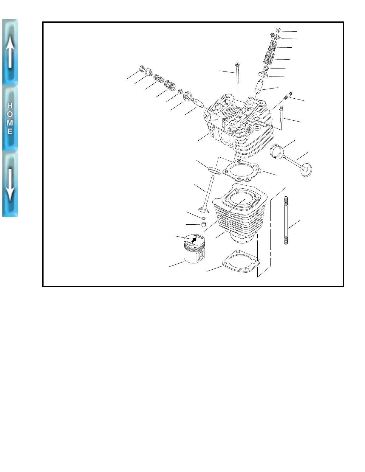
Figure 3-9. Cylinder Head, Cylinder and Piston
18
7
8
5
6
11
9
16
17
10
14
2
10
12
4
13
19
3
15
17
8
5
7
1
16
5
6
11
9
20
1. Head screw, long (2)
2. Head screw, short (2)
3. Arrow, piston direction
4. Head gasket
5. Inner valve spring (2)
6. Outer valve spring (2)
7. Valve keeper (4)
8. Upper collar (2)
9. Lower collar (2)
10. Valve (1 intake, 1 exhaust)
11. Valve stem seal (2)
12. Stud (4)
13. Base gasket
14. O-ring (2)
15. Insert/Dowel (2)
16. Valve guide (2)
17. Valve seat (2)
18. Cylinder head
19. Cylinder
20. Piston
xlhcylhead
10. Support motorcycle under front header mount. Do not
allow engine to drop when performing Step 11.
11. Continue loosening in 1/8-turn increments until screws
are loose. Remove screws and thick washers.
12. See Figure 3-9. Remove cylinder head (18), head gasket
(4), and O-rings (14).
NOTE
Front cylinder must be removed through upper triangular
frame members with front isolator mount attached.
13. See Figure 3-10. Remove socket screws (11), washers
(13), and retainers (9). Remove push rod covers (7),
seals (8), O-rings (10) and push rods (12). Mark the loca-
tion and orientation (top and bottom) of each push rod.
14. Remove socket screw (5), washer (14) and plate (4).
Remove O-rings (3) from ends of pins (2). Grasp pins (2)
and pull from crankcase. Use a pliers if necessary.
Remove lifter from crankcase bore.
15. Repeat Steps 1-13 for the other head.
DISASSEMBLY
NOTE
Disassembly of front cylinder exhaust valve components
requires front isolator mount removal.
1. See Figure 3-9. Compress valve springs (5, 6) with
VALVE SPRING COMPRESSOR (Part No. HD-34736B)
(as shown in Figure 3-11.)
2. Remove keepers (7), upper collar (8) and springs (5, 6).
Mark keepers for reassembly in original position.
3. Use a fine tooth file to remove any burrs on the valve
stem at the keeper groove.
4. Mark valve to ensure that it will be reassembled in the
same head. Remove valve (10), valve stem seal (11) and
lower collar (9).
5. Repeat Steps 1-5 for the other valve.
6. Disassemble the other head following Steps 1-6.