3-14
CLEANING, INSPECTION
AND REPAIR
1. Bead blast or scrape carbon from head, top of cylinder
and valve ports. Be careful to avoid scratching or nicking
cylinder head and cylinder joint faces. Blow off loosened
carbon or dirt with compressed air.
2. Soak cylinder head in an aluminum-compatible cleaner/
solvent to loosen carbon deposits.
3. Wash all parts in non-flammable solvent, followed by a
thorough washing with hot, soapy water. Blow out oil pas-
sages in head. Be sure they are free of sludge and car-
bon particles. Remove loosened carbon from valve head
and stem using a wire wheel. Never use a file or other
hardened tool which could scratch or nick valve. Polish
valve stem with very fine emery cloth or steel wool.
4. Check each rocker arm, at pad end and push rod end, for
uneven wear or pitting. Replace rocker arm if either con-
dition exists.
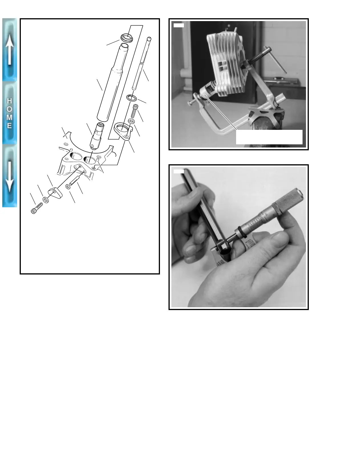
5. See Figure 3-12 and Figure 3-13. Measure rocker arm
shaft diameter at the positions where shaft fits in lower
rocker arm cover and where rocker arm bushings ride.
Record the measurements.
6. See Figure 3-14 and Figure 3-15. Measure rocker arm
shaft bore diameter in lower rocker cover and rocker arm
bushing inner diameter. Record the measurements.
7. Check the clearances and measurements obtained in
Steps 5 and 6 against the SERVICE WEAR LIMITS.
Repair or replace parts exceeding the SERVICE WEAR
LIMITS.
8. Assemble rocker arms and rocker arm shafts into lower
rocker cover.
Figure 3-10. Middle Valve Train Components
(Quantities per Engine Cylinder)
1. Right
crankcase half
2. Pin (2)
3. O-ring (2)
4. Plate
5. Screw
6. Tappet lifter (2)
7. Push rod cover (2)
8. Seal (2)
9. Retainer (2)
10. O-ring (2)
11. Screw (2)
12. Push rod (2)
13. Washer (2)
14. Washer
15. Locating pin (2)
b0134x3x
5
14
4
6
7
1
3
2
9
13
15
11
8
12
10
Figure 3-11. Compressing Valve Springs
Figure 3-12. Measuring Rocker Arm Shaft Diameter
(Rocker Cover Position)
Valve Spring Compressor
(Part No. HD-34736B)
5694
2767a