7-9
Ignition Resistance Test-Ignition Module Harness
TEST
METER
SETTING
PROBE 1 PROBE 2 METER READING AT HARNESS
Check for
grounds
RX1
To pin 8 on
connector [P10]
To chassis
ground
0-1 Ohm Good.
More than
1 Ohm
Repair/clean ground connection.
Check for
grounds
RX1
All pins except
pin 8 on
connector [P10]
To chassis
ground
Infinity Good.
Any
resistance
Locate and repair short to ground.
Continuity RX1
All pins except
pin 8 on
connector [P10]
Opposite end of
each of the 6
leads
0-1 Ohm Good.
More than
1 Ohm
Repair broken wire or loose/dirty
connection
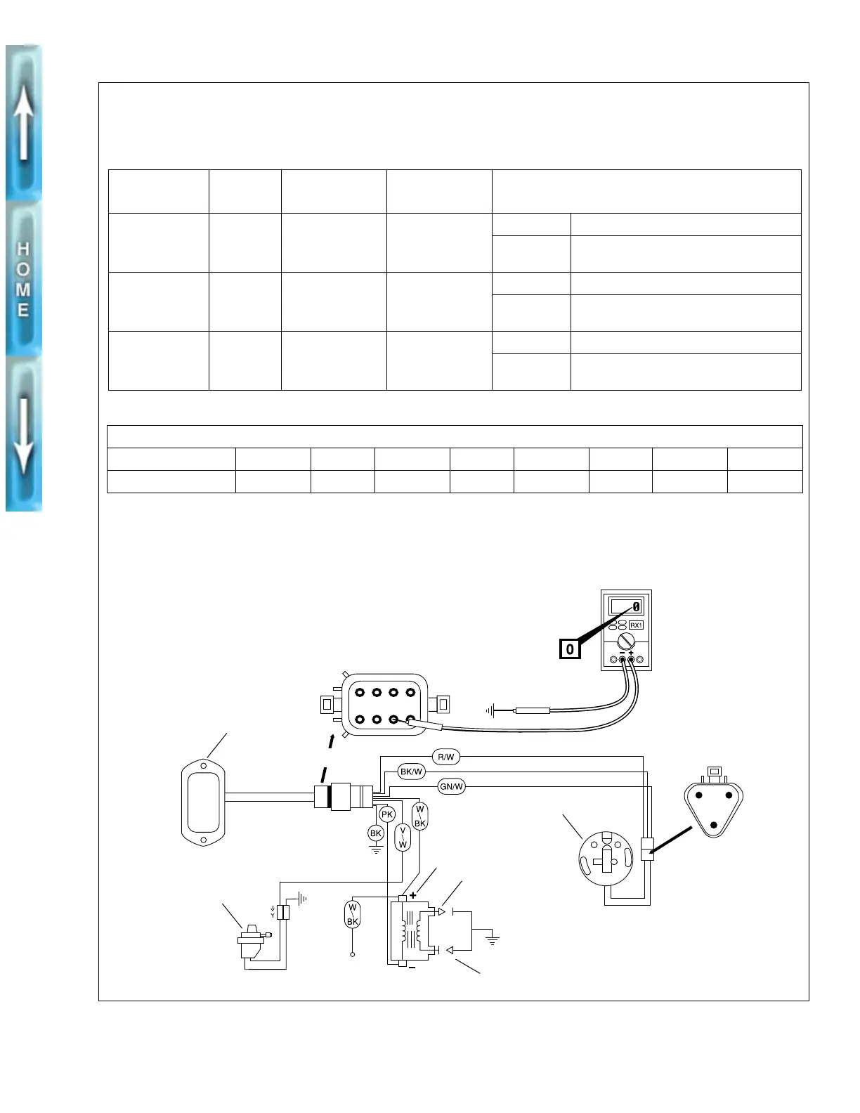
IGNITION MODULE CONNECTOR [P10]
PIN NO. 1234567 8
COLOR CODE
W BK/W R PK GN V/W BK open
f1143b8x
TEST CONDITIONS: Engine stop switch on right handlebar must be in OFF position and 8-place ignition module
connector [P10] and 3-place sensor connector [P16] must be disconnected for these tests. Shake or wiggle the
harness to detect any breaks in the wiring.
BA
C
43
2
1
56
7
8
Chassis
ground
1. Ignition sensor plate
2. Ignition module
3. Ignition coil
4. Spark plug
5. Vacuum-operated electric
switch (V.O.E.S.)
2
5
3
4
1
4
Unplug
A. Red
B. Green
C. Black
3-pin black ignition
sensor [P16]
8-pin black ignition
module sensor [P10]