145I-Modell - 11/12 - Ausgabe 09/11 - 2096165 - BUE-0056-05EN
Electrical system
8
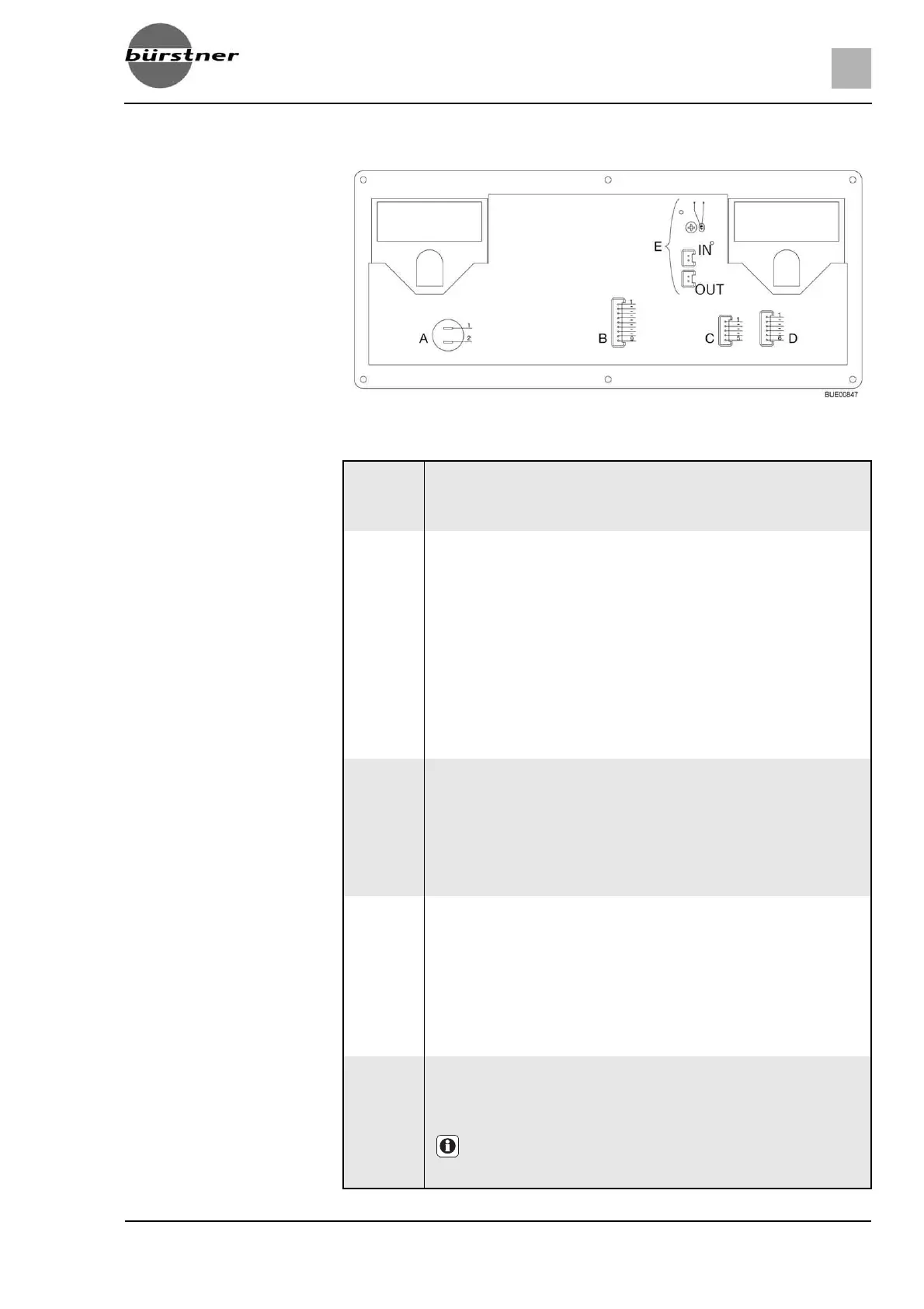
Fig. 153 Block diagram for panel (IT 994)
A
1
2
2 x AMP flat pins 4.8 x 0.8
+ 12 V
Pump
B
1
2
3
4
5
6
7
8
9
Lumberg MSFQ 9-pin
12 V indicator
12 V main switch off
12 V main switch on
+ Starter battery 12 V
+ Living area battery sensor
Negative living area battery sensor
230 V indicator
Shunt for appliances
Shunt battery
C
1
2
3
4
5
Lumberg MSFQ 5-pin
Full
3/4
1/2
1/4
Base waste water tank
D
1
2
3
4
5
6
Lumberg MSFQ 6-pin
Full
3/4
1/2
1/4
Base water tank
n. c.
E
IN
OUT
2 x Lumberg MSFQ 2-pin plugs
External internal temperature sensor (optional)
External temperature sensor
Z If an external internal temperature sensor is used, both gray
stranded wires of the internal internal temperature sensor
are separated.
 Loading...