Chapter 2 BK730-2 Base Page 2-14
2.2.4.1 Dip Switch Settings
The Speed Control Board has two 8 position DIP switches used to configure its operating
mode based on the system’s setup requirements and position in the Production line. Table
2-3 and Table 2-4 list the switch assignments for DIP S2 and S3 respectively.
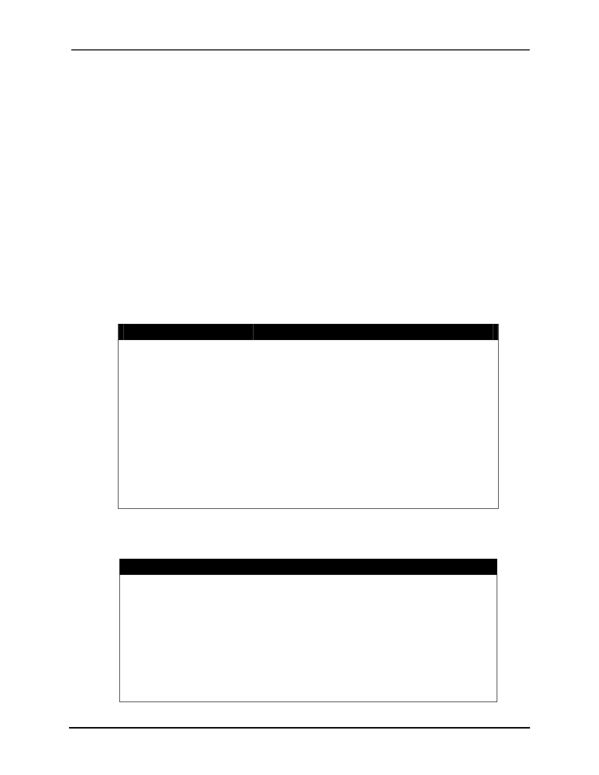
Table 2-3: DIP switch setting definitions for DIP S2.
Switch Position(s) Description
Position 1
On if Photo 1 is Normally Closed
Position 2 On if Photo 2 is Normally Closed
Position 5, 6 Feedback Encoder Resolution as follows
5:6 = Off:Off 660 DPI
5:6 = On:Off 600 DPI
5:6 = Off:On Not Used
5:6 = On:On Not Used
Position 7, 8 Follower Encoder Resolution as follows
7:8 = Off:Off 660 DPI (Or for last Transport)
7:8 = On:Off 600 DPI
7:8 = Off:On Not Used
7:8 = On:On Not Used
Table 2-4:
DIP switch setting definitions for DIP S3.
Switch Position(s) Description
Position 1
On to calibrate for 0 m/s
Position 2
On to calibrate for 1 m/s
Position 3
On to calibrate for 17 inch pitch
Position 4
On for “Follower” operating mode
Position 5
On for “Gap Control” operating mode
Position 6
Not Used
Position 7
Not Used
Position 8
On for “Master Follower” operating mode
Note: Only 1 switch can be enabled at any given time for DIP S3.
Buskro Ltd. BK730-2 Tabber