b. Tighten the power supply cable connector.
c. Verify that the F1 and F2 fuse housings on the power block are open (Figure 4.8, page 75).
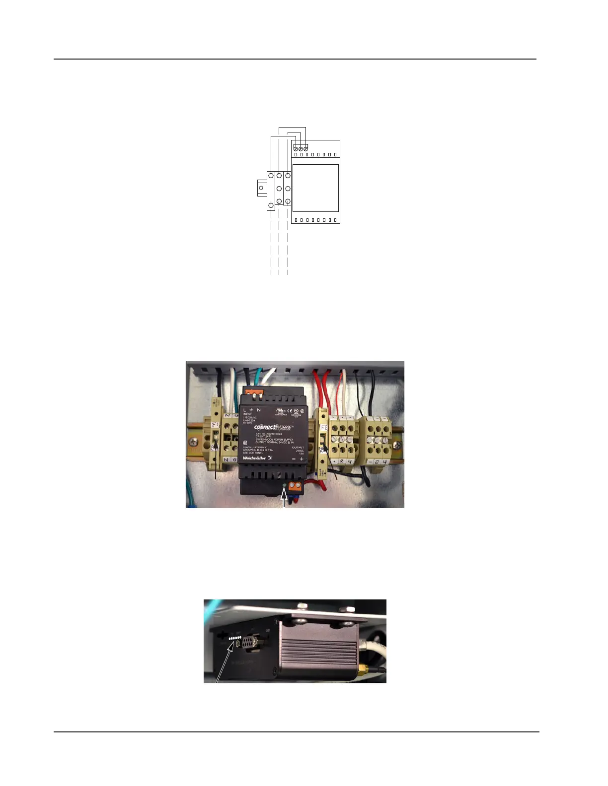
d. Wire the external power supply to the designated terminal blocks (H, N, GND) as shown in Figure 4.9.
110/240 VAC
B W G
F1
H N
GND
Figure 4.9—WiFi box external power supply wiring diagram
6. Restore the external power that was disconnected in step 2 to initiate power to the WiFi box.
7. Close the F1 fuse housing (Figure 4.10) to bring power into the box. The green indicator light on the modem power
supply will come on to indicate that the fuse is working correctly.
F1 fuse
diode light
F2 fuse
diode light
Modem power
Figure 4.10—F1 and F2 fuse housing, closed
8. Close the F2 fuse (Figure 4.10) to supply power to the modem and the connected Scanner 3100.
9. Verify that the modem indicator lights are illuminated (Figure 4.11). If no lights are visible, check the diode light in
the middle of the fuse housing (Figure 4.10). If it is lit, the fuse is blown and must be replaced.
Figure 4.11—Location of modem indicator lights
76
Section 4 Scanner 3100 EFM