e. To free up space for pulling wires through the conduit port, unseat the terminal board by unscrewing the four
Phillips screws holding it in place and gently pulling the board straight back to disconnect it from its connected
header without bending pins. Do not attempt to completely remove the board from the enclosure. Doing so
could damage a SATA cable attached to the back of the terminal block. Allow the board to rest terminal-side up
along the bottom edge of the enclosure.
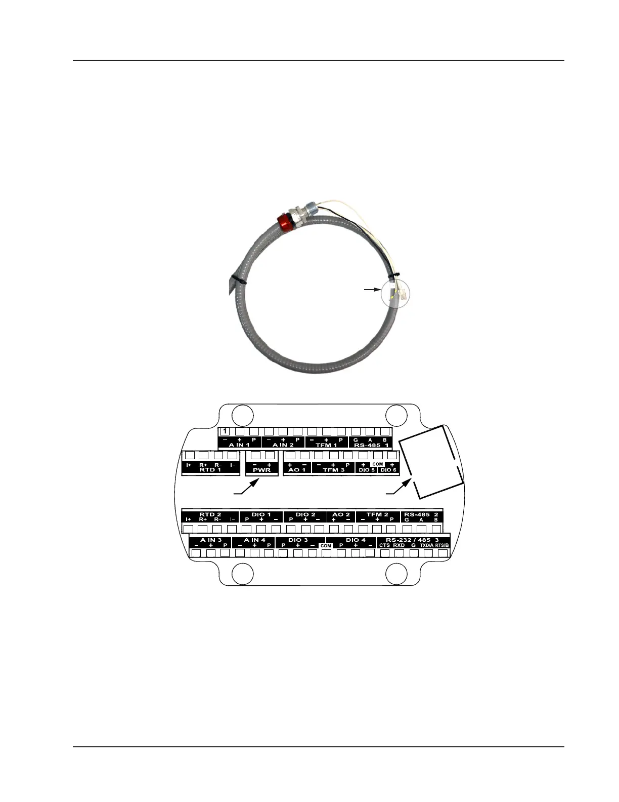
f. Thread the Ethernet and power wires shown in Figure 4.7 through the conduit opening in the Scanner 3100
enclosure and tighten the cable connector in the conduit opening.
g. Connect the Ethernet cable to the Ethernet port on the Scanner 3100 terminal board (shown in Figure 4.8).
Ethernet and
power connectors
Figure 4.7—Ethernet and power conductors connecting the WiFi box to the Scanner 3100
Power Ethernet
2 3 4 5 6 7 8 9 10 11 12
13 14 15 16 17 18 19 20 21 22 23 24 25 26
27 28 29 30 31 32 33 34 35 36 37 38 39 40 41 42 43 44
45 46 47 48 49 50 51 52 53 54 55 56 57 58 59 60 61 62
Figure 4.8—Terminal board illustration showing Ethernet port and Power terminal block location
h. Wire white (+) and black (–) power wires to the Scanner 3100 PWR terminal block (shown in Figure 4.7).
i. Reseat the terminal block in the enclosure, carefully aligning the pins on the back with the underlying header,
and replace the four screws removed in step 4c.
j. Replace the Scanner 3100 enclosure lid.
5. With the external power still off, connect the 110 VAC external power supply to the WiFi box as follows:
a. Thread the external power supply wires through the conduit hub on the bottom of the WiFi box (Figure 4.4,
page 73).
75
Scanner 3100 EFM Section 4