CDE360 Vector Control AC Drive Chapter 3 Mechanical and Electrical Installation
Function Description of the Terminals on Control Board
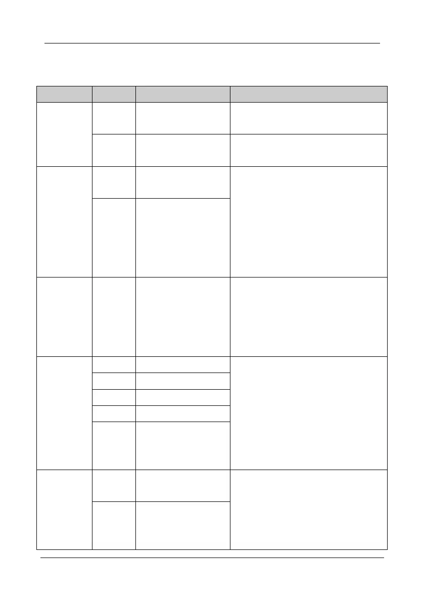
Table 3- 5 Function description of the terminals on control board
10V Reference Power Supply
10V/30mA,usually is used for the power supply of
the analog signal.
24V/200mA,usually is used for the power supply of
the digital signal.
Input range: -10V~10V/0~20mA,decided by the
jumper.
Input resistance: 120KΩ (voltage input), 250Ω
(current input).
Jumper CJ1 on the control board is used for AI1
and jumper CJ2 on the control board is used for
AI2.
Voltage Input range: 0~10V; load≤10mA.
Current Input range: 0~20mA; load≤500Ω.
The output signal can be used for the voltage or
current type.
Jumper CJ3 on the control board is used for AO1
1) Optical coupling isolation, compatible with dual
polarity input.
2) Input resistance: 4.7KΩ.
3) Input voltage range: 9~30V.
4) X6/FI can be used for common digital input
terminal and be compatible with high-speed
pulse (0~100KHz) input.
Digital Input Terminal
6&high-speed pulse input
terminal
Digital output terminal 1
1) Optical coupling isolation, open collector output.
2) Output voltage and current: 24VDC, ≤50mA.
Running frequency: < 500Hz.
Y2/FO can be used for common digital output
terminal, at the same time, it can also be used for
Digital output terminal 2 &
high-speed pulse output
terminal