Installing the Router 3-119
Installing Power Supplies
Installing Power Supplies
You will install one or two, AC-input or DC-input power supplies in the upper and lower power
supply bays in the rear of the chassis. Always install the first power supply in the lower power supply
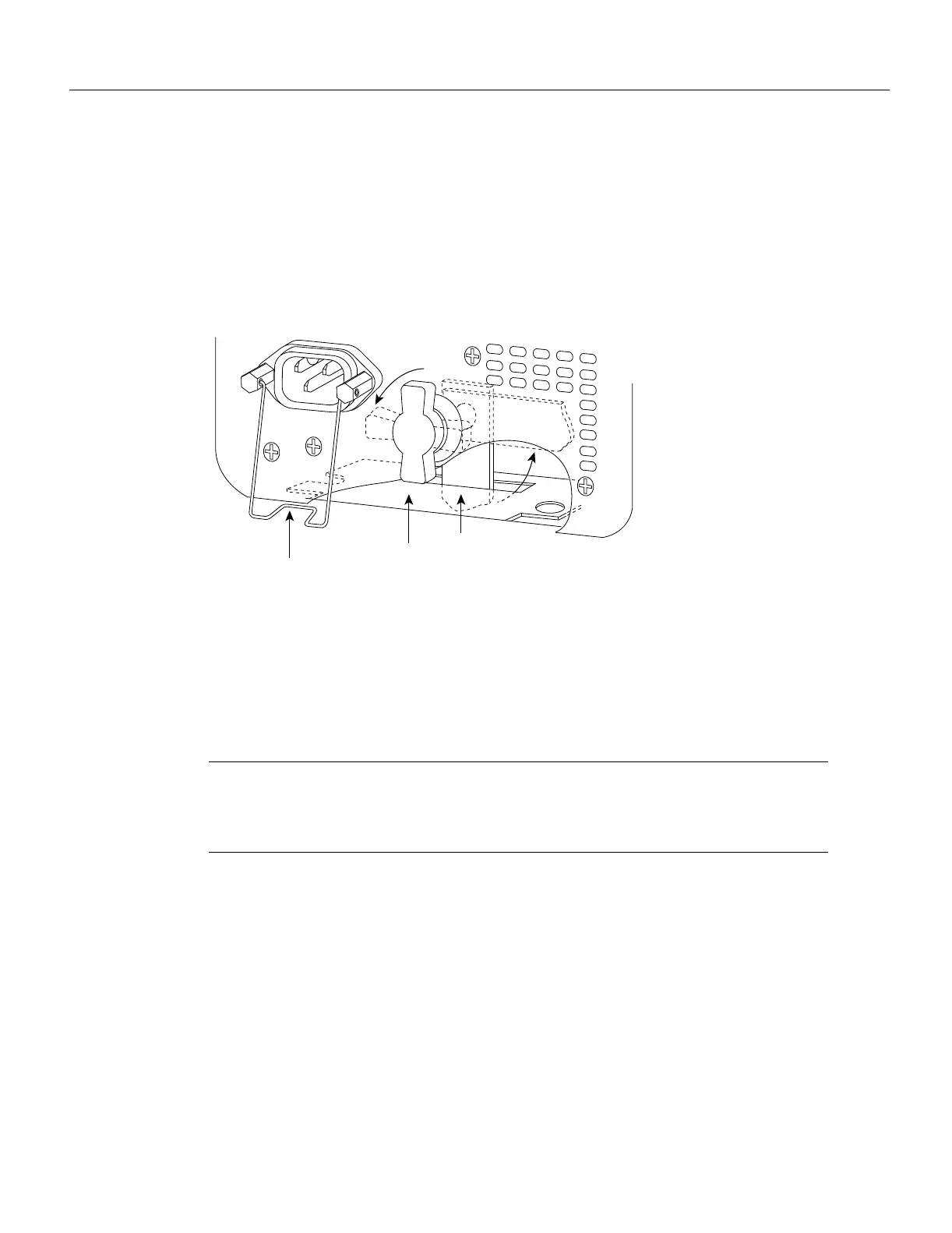
bay and the second, if any, in the upper bay. The power supply switch is also an interlock tab. (See
Figure 3-1.) When the switch is in the on (|) position, the tab extends into a slot in the chassis to
prevent the power supply from being removed accidentally or from falling out of the chassis.
Figure 3-1 Power Supply Interlock —AC-Input Power Supply Shown
Before proceeding, ensure that you have sufficient working space (3 to 4 feet) behind the chassis and
that access to the power supply bays is not blocked by an equipment rack power strip or cables from
other equipment. If cables from other equipment are in the way, move them aside and temporarily
secure them with tie wraps before proceeding. Keep in mind that cables that block access to the bays
may also block the power supply LEDs from view. If a power strip or other rack fixture is in the way,
you may need to loosen the chassis ears from the equipment rack-mounting strips and carefully push
the chassis out of the rack until you can maneuver each power supply into a bay.
Note The power strips provided in some equipment racks might partially block access to the
chassis power supply bay. If so, you will have to slide the front of the chassis out of the rack far
enough to allow the power supplies to clear the power strip. Steps for doing so are included in the
procedures that follow.
Tools Required
You need the following tools to complete this procedure:
• A 1/4-inch flat-blade or number 2 Phillips screwdriver to install the power supply. Earlier power
supplies (the first few hundred shipped) have a slotted-head captive installation screw.
• If the chassis is mounted in an equipment rack, and cables from other equipment fall in front of
the power supply bays, you will need cable ties to temporarily anchor the cables out of the way.
• If access to the power supply bays is partially blocked by a power strip or other permanent rack
fixture, you will need a 3/16-inch flat-blade screwdriver to temporarily detach the ears from the
equipment rack-mounting strips.
Before beginning the power supply installation, note the type of the installation screws on all power
supplies, and check the area around the power supply bays to determine which tools you will need.
Safety interlock
switch
Locking device
in ON and
locked positions
I
O
H1315a
Cable-retention clip

 Loading...


