5-242 Cisco 7000 Hardware Installation and Maintenance
Replacing Internal Components
Replacing the Chassis Blower
The chassis blower draws cooling air in through the chassis bottom front panel and sends it up
through the floor of the inner rear compartment to cool the RP, SP (or SSP), and interface processors.
The absence of cooling air can cause the interior of the chassis to heat up and may cause an
overtemperature condition.
Caution Never operate the system if the blower is not functioning properly or if one is not installed.
An overtemperature condition can result in severe equipment damage.
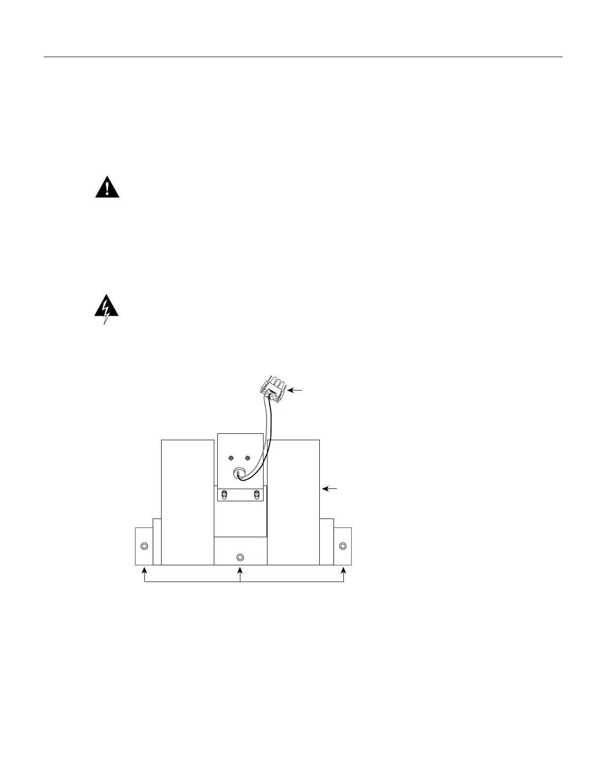
The blower is located at the bottom of the chassis interior. (See Figure 5-30.) Two air ducts on the
rear of the blower, shown shaded in the illustration, fit snugly into the two cutouts in the backplane.
The blower is secured to the backplane with three large captive Allen-head screws, which are shown
in Figure 5-32.
Warning Before accessing the chassis interior, turn off the power switch and unplug the power
cord. Use extreme caution when working near the backplane; high voltage is present when the
system is operating.
Figure 5-32 Chassis Blower
Black (ground)
Purple (+24V)
Captive Allen-head screws
Blower power
connection
Blower
H1386a

 Loading...


