Reading LED Indicators B-267
RSP7000 LEDs
RSP7000 LEDs
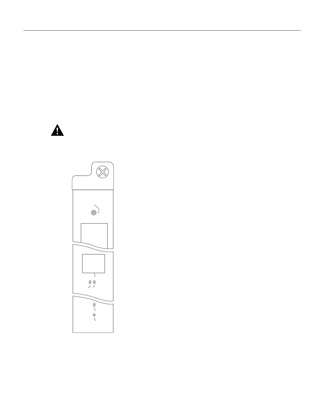
Figure B-5 shows the LEDs on the RSP7000 faceplate. The LEDs on the RSP7000 indicate the
system and RSP7000 status and which Flash memory card slot is active. The CPU halt LED, which
goes on only if the system detects a processor hardware failure, should remain off. A successful boot
is indicated when the normal LED goes on; however, this does not necessarily mean that the system
has reached normal operation. During normal operation, the CPU halt LED should be off, and the
normal LED should be on.
The slot 0 and slot 1 LEDs indicate which PCMCIA (Flash memory) card slot is in use, and each
LED blinks when the card is accessed by the system.
Caution The reset switch resets the RSP7000 and the entire system. To prevent system errors and
problems, use it only at the direction of your service representative.
Figure B-5 RSP7000 LEDs
NORMAL
RESET
CPU HALT
H5378
EJECT
SLOT 1
SLOT 0

 Loading...


