Preparing for Installation 2-83
Site Requirements
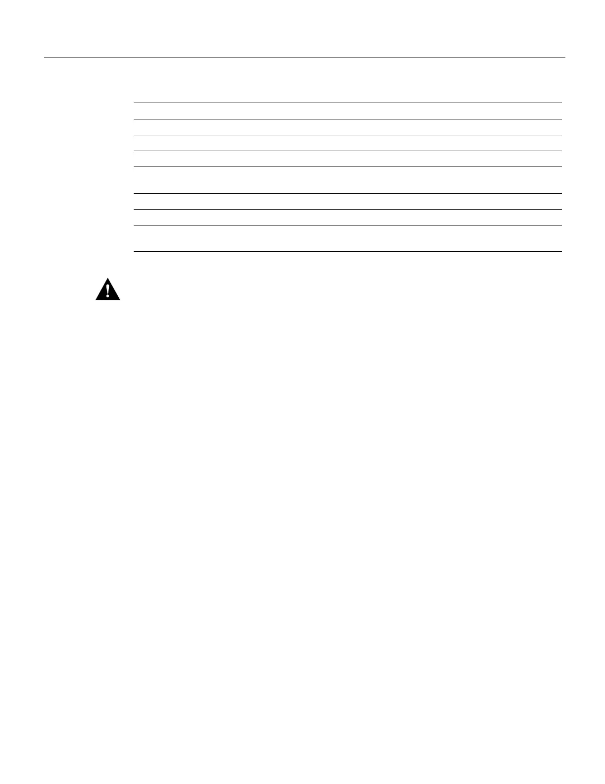
Table 2-12 Specifications for Operating and Nonoperating Environments
Caution
Keep the air filter clean to maintain normal airflow through the system.
Preventive Site Configuration: Maintaining Normal Operation
Planning a proper location for the router and the layout of your equipment rack or wiring closet are
essential for successful system operation. Equipment placed too close together or inadequately
ventilated can cause system overtemperature conditions. In addition, chassis panels made
inaccessible by poor equipment placement can make system maintenance difficult. Following are
precautions that can help avoid problems during installation and ongoing operation.
General Precautions
Follow these general precautions when planning your equipment locations and connections:
• Use the show environment command regularly to check the internal system status. The
environmental monitor continuously checks the interior chassis environment and provides
warnings for high temperature and maximum and minimum voltage, and reports on occurrences.
If warning messages are displayed, take immediate action to identify the cause and correct the
problem. (Refer to the section “Environmental Reports” in the chapter “Product Overview.”
• Keep the front of the chassis free from obstructions and away from the exhaust air of other
equipment. Remember that electrical equipment generates heat, and ambient room temperature
alone may not be adequate to cool equipment to acceptable operating temperatures.
• Keep the air filter clean. Do not place the router directly on the floor or in any area that tends to
collect dust.
• Follow ESD prevention procedures to avoid damage to equipment. Damage from static discharge
can cause immediate or intermittent equipment failure.
• Ensure that the chassis panels, interface processors, and any interface processor slot fillers are in
place and secure. The blower directs cooling air across the interface processors and forces it out
between the interface processor faceplates; a loose panel allows too much air to escape and can
redirect the airflow away from active interface processors.
Minimum Maximum
Temperature, ambient operating 32°F (0°C) 104°F (40°C)
Temperature, ambient nonoperating and storage –4°F (–20°C) 149°F (65°C)
Humidity (RH), ambient (noncondensing) operating 10% 90%
Humidity (RH), ambient (noncondensing) nonoperating
and storage
5% 95%
Altitude, operating and nonoperating Sea level 10,000' (3050 m)
Vibration, operating 5–200 Hz, 0.5 g (1 oct./min.)
Vibration, nonoperating 5–200 Hz, 1 g (1 oct./min.)
200–500 Hz, 2 g (1 oct./min.)

 Loading...


