1-18 Cisco 7000 Hardware Installation and Maintenance
Physical Description
• OIR—Online insertion and removal, the feature that allows you to replace interface processors
and redundant power supplies without interrupting system power
• PA—Port adapter, for example the FSIP or MP daughter card
• RP—Route Processor, the system processor board
• RSP7000—7000 Series Route Switch Processor
• RSP7000CI—7000 Series Chassis Interface
• SP—Switch Processor, the CxBus traffic controller
• SSP—Silicon Switch Processor, the CxBus traffic controller
• TRIP—Token Ring Interface Processor
Physical Description
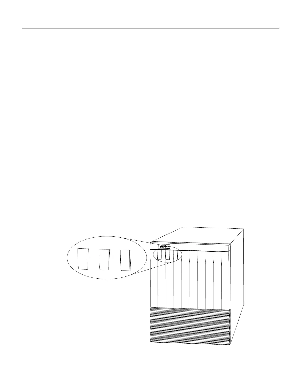
The router front panel, shown in Figure 1-1, contains three status indicators and two removable
panels for access to the internal components. The three-light emitting diodes (LEDs) on the front
panel indicate normal system operation and the currently active power supplies. On the back of the
router, additional LEDs on the RP and power supplies indicate the same status. The normal LED
lights to indicate that the system is in a normal operating state. The upper power and lower power
LEDs light to indicate that a power supply is installed in the indicated power supply bay and is
providing power to the system. The power LEDs go out if the power supply in the corresponding bay
reaches an out-of-tolerance temperature or voltage condition. (For descriptions of thresholds and
status levels, refer to the section “Environmental Monitoring and Reporting Functions” in this
chapter.) The front panel normal LED is controlled by the RP, which contains an identical normal
LED that can be seen from the rear of the router.
Figure 1-1 Router Front View
UPPER
POWER
LOWER
POWER
NORMAL
Cisco 7000
H1316a
UPPER
POWER
LOWER
POWER
NORMAL

 Loading...


