Preparing for Installation 2-93
Preparing Network Connections
Fast Ethernet Connection Equipment
The two connectors on the FEIP port adapter are a single MII, 40-pin, D-shell type, and a single
RJ-45. You can use either one or the other. Only one connector can be used at one time. The FEIP
can have up to two port adapters installed. Each connection supports IEEE 802.3u interfaces
compliant with the 100BaseX and 100BaseT standards. The RJ-45 connection does not require an
external transceiver; however, the MII connection does depending on the type of connection you use.
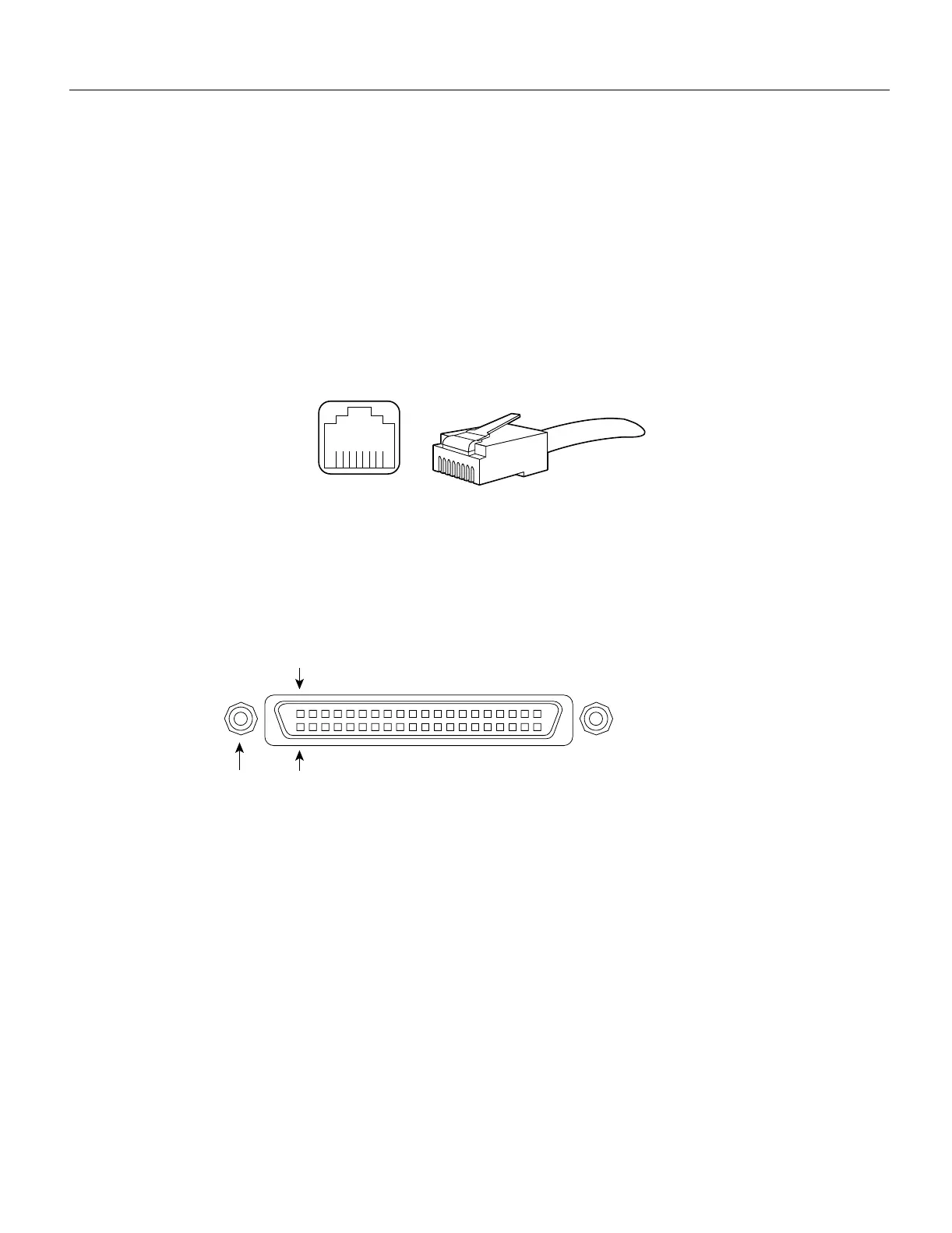
The RJ-45 modular connector (see Figure 2-17) has strain relief functionality incorporated into the
design of its standard plastic connector. Figure 2-17 and Figure 2-18 show the RJ-45 and MII
connectors.
Figure 2-17 RJ-45 Connections—Connector and Plug
Depending on the type of media you use between the MII connection on the port adapter and your
switch or hub, the network side of your 100BaseT transceiver should be appropriately equipped:
with ST-type connectors (for optical fiber), BNC connectors (for 10Base2 coaxial cable), and so
forth. Figure 2-18 shows the pin orientation of the female MII connector on the port adapter.
Figure 2-18 MII Connection—Female
The MII receptacle uses 2-56 screw-type locks, called jackscrews (shown in Figure 2-18), to secure
the cable or transceiver to the MII port. MII cables and transceivers have knurled thumbscrews
(screws you can tighten with your fingers) that you fasten to the jackscrews on the FEIP MII
connector. Use the jackscrews that are appropriate for your MII cable.
Token Ring Connection Equipment
You will need an 802.5 MAU and Token Ring adapter cable between each TRIP port and the network
ring. The Token Ring connectors on the TRIP are DB-9 (PC type) receptacles that require an
interface cable with a 9-pin DB-9 plug at the TRIP end and a MAU connector at the network end.
Both connectors are shown in Figure 2-19.
H2936
8 7 6 5 4 3 2 1
RJ-45 connector
Jackscrew Pin 1
Pin 21
H2943

 Loading...


