EasyManuals Logo

Cisco 7000 Hardware Installation And Maintenance

Cisco 7000
319 pages
To Next Page IconTo Next Page
To Previous Page IconTo Previous Page
Page #275 background imageLoading...
Page #275 background image
Reading LED Indicators B-271
Interface Processor LEDs
EIP LEDs
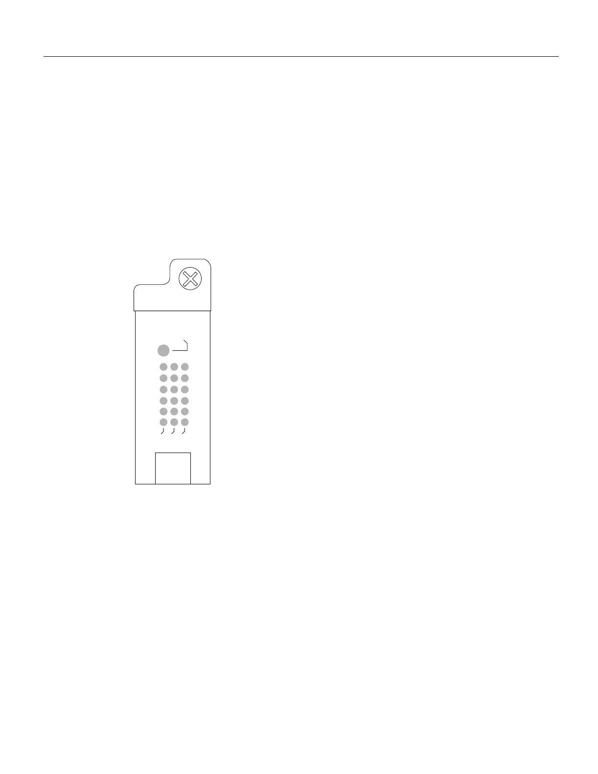
The EIP contains a bank of 18 LEDs: one horizontal row of 3 LEDs for each of the 6 Ethernet
interfaces, as shown in Figure B-8.
As with the other interface processors, the enabled LED goes on to indicate that the EIP is enabled
for operation. Three LEDs for each port indicate the following:
• Collision—A frame collision has been detected.
• Transmit—Frames are being transmitted.
• Receive—Frames are being received.
Figure B-8 EIP LEDs
H1365a
ENABLED
0
1
2
3
4
5
RECEIVE
TRANSMIT
COLLISION

Table of Contents

Other manuals for Cisco 7000

Questions and Answers:

Question and Answer IconNeed help?

Do you have a question about the Cisco 7000 and is the answer not in the manual?

Cisco 7000 Specifications

General IconGeneral
Product TypeSwitch
Model7000
CategorySwitch
PortsVaries by configuration
Power SupplyRedundant power supplies supported
ManagementSNMP, CLI

Related product manuals