Installing the Router 3-141
Starting the Router
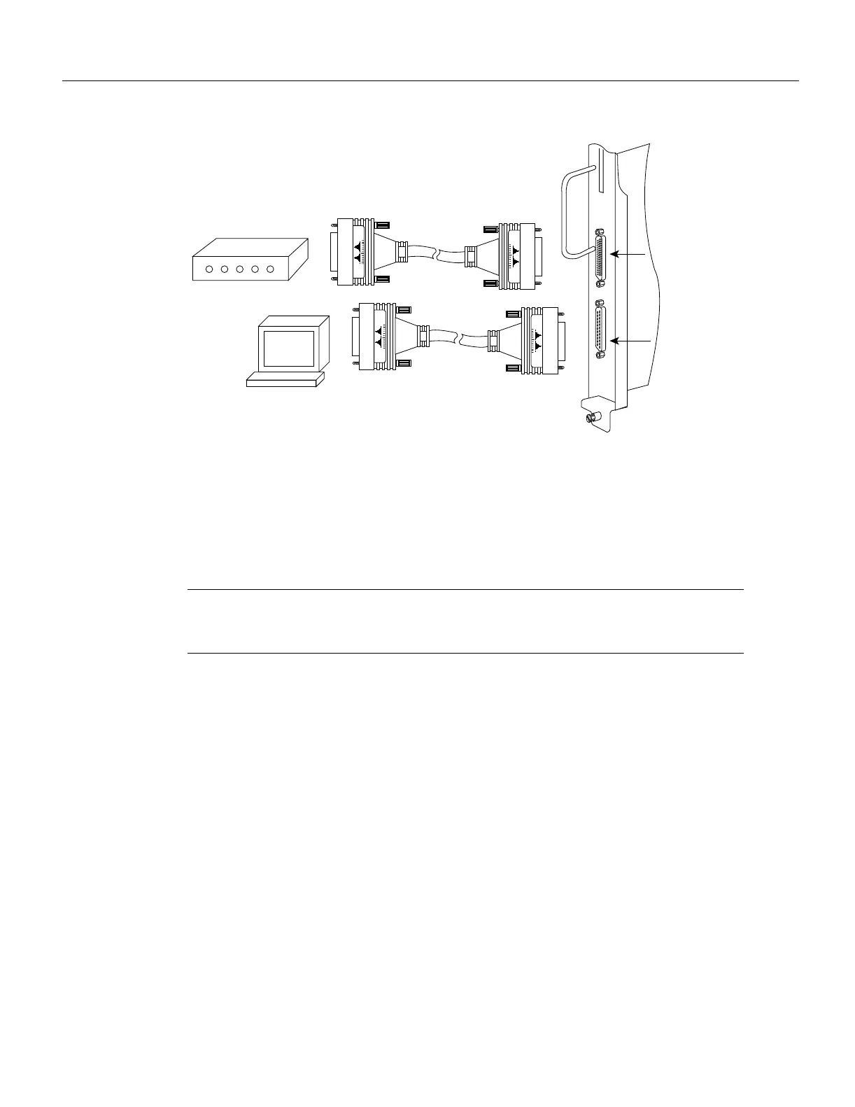
Figure 3-22 Console and Auxiliary Port Connections
Connecting Auxiliary Port Equipment
The auxiliary port is a DB-25 plug DTE port for connecting a modem or other DCE device (such as
a CSU/DSU or other router) to the router. The port is located on the RP (or RSP7000) above the
console port and is labeled Auxiliary. An example of a modem connection is shown in Figure 3-22.
Note Both the console and auxiliary ports are asynchronous serial ports; any devices connected to
these ports must be capable of asynchronous transmission. (Asynchronous is the most common type
of serial device; for example, most modems are asynchronous devices.)
Starting the Router
When all interfaces are connected, perform a final check of all connections, then power up the
system as follows:
Step 1 Check the following components to make sure they are secure:
• Each interface processor is inserted all the way into its slot, and all of the captive
installation screws are tightened.
• All interface cable connections are secured.
• The Flash memory card, if present, is inserted all the way into its slot on the RP (or
RSP7000).
• Each power supply is inserted all the way into its bay, and the captive installation screw
is tightened.
• All power-supply cables are connected to the power supply and secured with the cable
retention clip (AC-input power supply) or two nylon cable ties (DC-input power
supply).
H1352a
Modem
Console terminal
Auxiliary
port
Console
port

 Loading...


