Product Overview 1-39
Physical Description
necessary in the future, refer to the section “Microcode Component Replacement” in the chapter
“Maintenance.” Specific instructions will also be provided with the replacement component in an
upgrade kit.
Each interface processor has a unique bank of status LEDs, and all have a common enabled LED at
the top of the interface processor face plate. The enabled LED lights when the RP has completed
initialization of the interface processor for operation, indicating that, as a minimum, the interface
processor is correctly connected to the backplane, that it is receiving power, and that it contains a
valid microcode version. If any of these conditions is not met, or if the initialization fails for other
reasons, the enabled LED does not light. Additional LEDs on each interface processor type indicate
the state of the interfaces.
The following sections describe each interface processor type. The appendix “Reading LED
Indicators” describes the specific LED states of each.
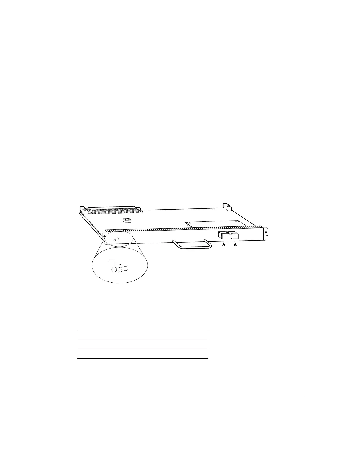
ATM Interface Processor (AIP)
The AIP for a Cisco 7000 series router provides a direct connection between the high-speed CxBus
and the external networks. (See Figure 1-12.) The physical layer interface module (PLIM) on the
AIP determines the type of ATM connection.
Figure 1-12 AIP with 100 Mbps UNI PLIM
Table 1-4 lists the maximum number of AIP modules supported on Cisco 7000 series routers. There
are no restrictions on slot locations or sequence; an AIP can be installed in any available interface
processor slot.
Table 1-4 Maximum AIP Modules by Chassis Model
Note Traffic from multiple ATM network interfaces could theoretically exceed the bandwidth of
the CxBus, causing packets to be dropped. Up to two AIP modules per Cisco 7000 is a practical
limit.
Chassis Maximum AIP Modules
Cisco 7000 (7-slot system) 5
Cisco 7010 (5-slot system) 3
H2337
UNI 155
U111, microcode ROM
TX RX
ENABLED
RX Carrier
RX Cells

 Loading...


