Installing the Router 3-133
Connecting Interface Cables
Dual Attachment Connections
A FIP that is connected as a dual attachment station (DAS) connects to both the primary and
secondary rings. The signal for each ring is received on one physical interface (PHYA or PHY B)
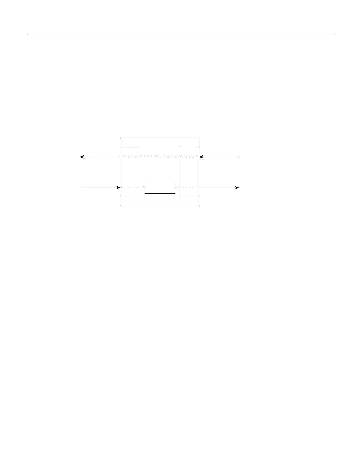
and transmitted from the other. The standard connection scheme (which is shown in Figure 3-11) for
a DAS dictates that the primary ring signal comes into the FIP on the PHYA receive port and returns
to the primary ring from the PHY B transmit port. The secondary ring signal comes into the FIP on
the PHY B receive port and returns to the secondary ring from the PHYA transmit port. Failure to
observe this relationship will prevent the FDDI interface from initializing. Figure 3-14 shows the
connections for a dual attachment that uses both multimode and single-mode fiber.
Figure 3-11 FDDI DAS Ports
Depending on whether you are connecting to a single-mode or multimode fiber network, connect the
FIP as follows:
• Single-mode—Observe the standard connection scheme described previously, and refer to
Figure 3-12 while you connect the interface cables as follows:
— Connect the cable coming in from the primary ring (from PHY B at the primary ring
upstream station) to the FIP PHYA receive port.
— Connect the cable going out to the primary ring (to PHYA at the primary ring downstream
station) to the FIP PHY B transmit port.
— Connect the cable coming in from the secondary ring to the FIP PHY B receive port.
— Connect the cable going out to the secondary ring to the FIP PHYA transmit port.
• Multimode—Each of the integrated transmit/receive multimode interface cables attaches to both
the primary and secondary ring; each one receives the signal from one ring and transmits to the
other ring. (See Figure 3-13.) To help avoid confusion, use the receive label on the cable MIC
connector as a key and connect the cables to the FIP ports as follows:
— Connect the cable coming in from the primary ring to the PHYA receive port. This also
connects the signal going out to the secondary ring to the PHYA transmit port.
— Connect the cable coming in from the secondary ring to the PHY B receive port. This also
connects the signal going out to the primary ring to the PHY B transmit port.
If you are connecting an optical bypass switch, proceed to the next section. Otherwise, proceed to
the section “Connecting the Console Terminal” later in this chapter.
TX
RX
PHY
A
RX
PHY
B
TX
Secondary Secondary
Primary Primary
FORMAC
H1550a

 Loading...


