Installing the Router 3-135
Connecting Interface Cables
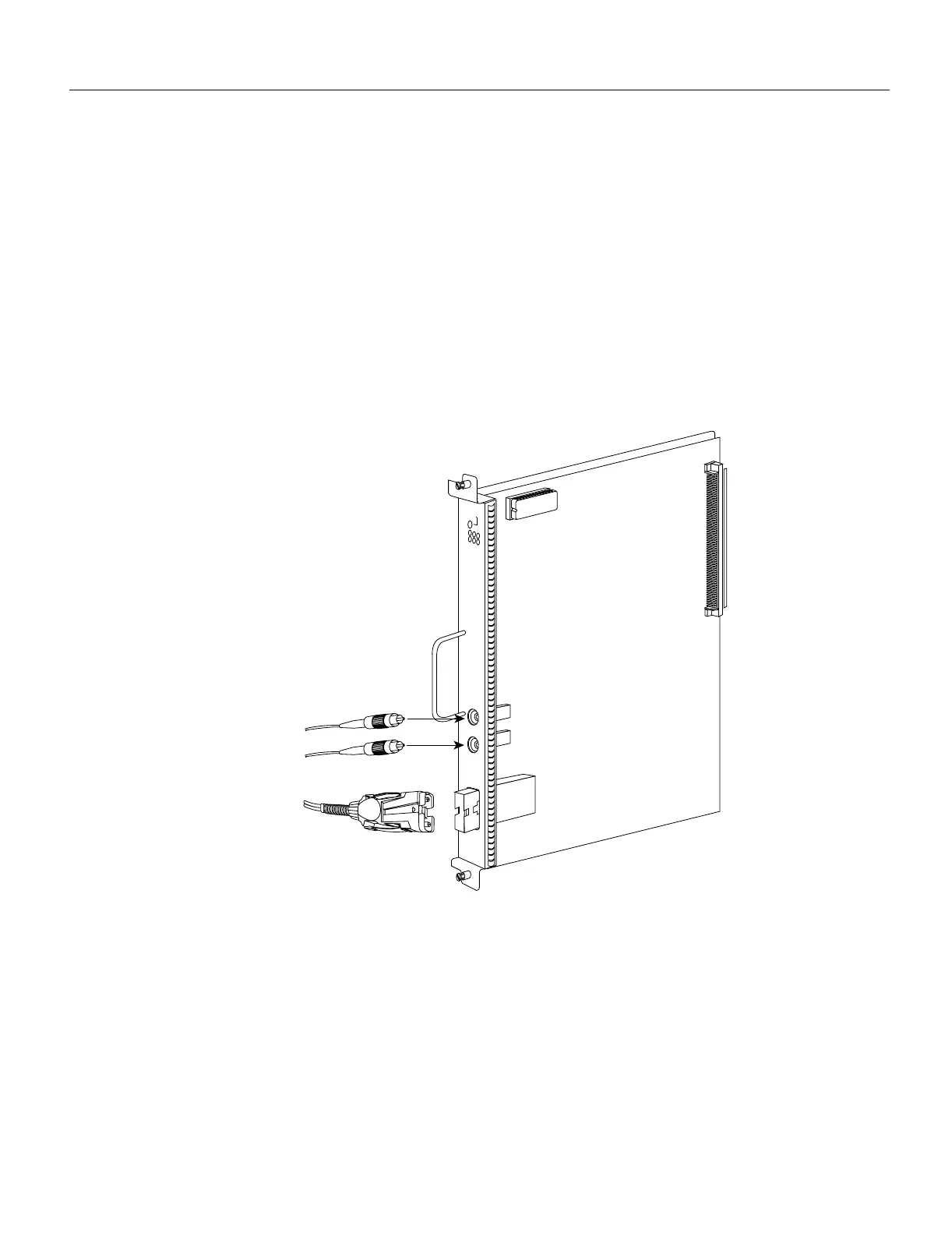
• Mixed mode—Follow the cabling guidelines described previously to connect the multimode and
single-mode interface cables. Figure 3-14 shows that the primary ring signal is received on the
multimode PHYA receive port and transmitted from the single-mode PHY B transmit port. Your
configuration may be the opposite, with multimode on PHY B and single-mode on PHYA.
Connect the cables to the FIP ports as follows:
— Connect the cable coming in from the primary ring to the PHYA receive port, and connect
the signal going out to the secondary ring to the PHYA transmit port.
— Connect the cable coming in from the secondary ring to the PHY B receive port. This also
connects the signal going out to the primary ring to the PHY B transmit port.
If you are connecting an optical bypass switch, proceed to the next section. Otherwise, proceed to
the section Connecting the Console Terminal later in this chapter.
Figure 3-14 FDDI Dual Attachment Network Connections, Single-Mode and Multimode
Installing an Optical Bypass Switch
An optical bypass switch is a device installed between the ring and the station that provides
additional fault tolerance to the network. If a FIP that is connected to a bypass switch fails or shuts
down, the bypass switch activates automatically and allows the light signal to pass directly through
it, bypassing the FIP completely. A port for connecting an optical bypass switch is provided on the
multimode/multimode FIP (CX-FIP-MM) and the single-mode/single-mode FIP (CX-FIP-SS) only.
(See Figure 3-15 for CX-FIP-MM connections and Figure 3-16 for CX-FIP-SS connections.)
H1731
U23
ENABLED
TX
RX
PHY B
PHY A
Transmit
Receive
o single-mode
network
To multimode
network
FC connectors (2)
MIC connector

 Loading...


