3-136 Cisco 700 Hardware Installation and Mainteneance
Connecting Interface Cables
The optical bypass control port on the FIP is a six-pin mini-DIN receptacle. Some optical bypass
switches use DIN connectors, and some use a mini-DIN. A DIN-to-mini-DIN control cable
(CAB-FMDD) is included with the FIP to connect optical bypass switches that use the larger DIN
connector. Up to 100 milliamperes of current can be supplied to the optical bypass switch.
Following are general instructions for connecting an optical bypass switch to the FIP; however, your
particular bypass switch may require a different connection scheme. Use these steps as a general
guideline, but refer to the instructions provided by the manufacturer of the switch for specific
connection requirements.
• Connect the bypass switch to the ring. Unless the documentation that accompanies the bypass
switch instructs otherwise, observe the same guidelines for connecting the A/B ports on the
bypass switch that you would to connect the ring directly to the FIP ports. Use the receive label
on the cable MIC connectors as a key and connect the cables to the network (ring) side of the
bypass switch as follows:
— Connect the cable coming in from the primary ring (from PHY B at the preceding station) to
the PHYA receive port on the network (ring) side of the bypass switch. This also connects
the signal going out to the secondary ring to the PHYA transmit port.
— Connect the cable coming in from the secondary ring (from PHYA at the preceding station)
to the PHY B receive port on the network (ring) side of the bypass switch. This also connects
the signal going out to the primary ring to the PHY B transmit port.
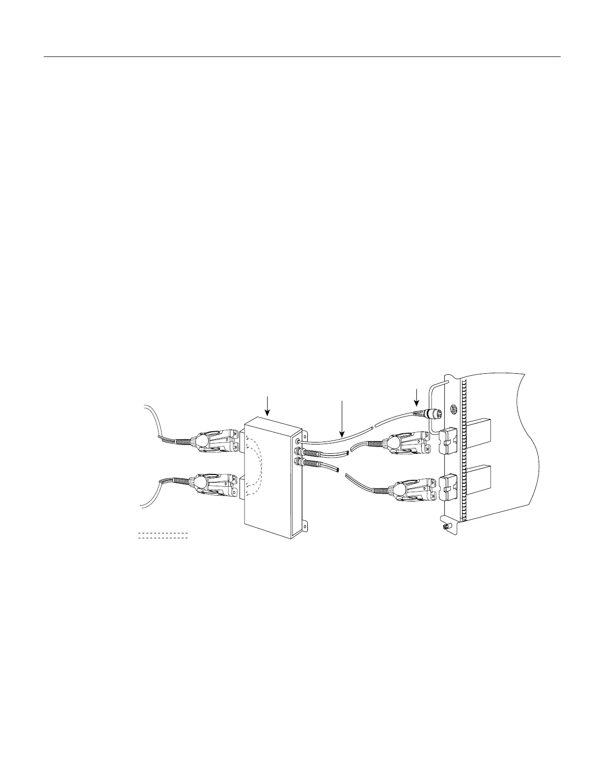
Figure 3-15 FDDI Connection with Optical Bypass—CX-FIP-MM
• Connect the bypass switch to the FIP. Unless the documentation that accompanies the bypass
switch instructs otherwise, consider the bypass an extension of the FIP ports and connect A to A
and B to B. The network cables are already connected to the bypass switch following the standard
B-to-A/A-to-B scheme.
— Connect an interface cable between the PHYA port on the station (FIP) side of the bypass
switch and the FIP PHYA port.
— Connect an interface cable between the PHY B port on the station (FIP) side of the bypass
switch and the FIP PHY B port.
H1342a
Mini-DINOptical bypass
control cable
Optical bypass
switch
A
B
PHY B
PHY A
Bypass operation
PHY A
PHY B
To
ring
CX-FIP-MM

 Loading...


